NOTE: These circuits do not improve human vision's sensitivity to LED light. Instead, they operate LEDs at instantaneous currents at which they are more efficient. This allows average current to be extremely low, where most LEDs work inefficiently if such a low current is in the form of steady DC.
These pulsing circuits are generally for operating LEDs at instantaneous current of ~1-6 milliamps, while average current is generally ~.03 to .2 milliamp.
This circuit as shown draws about 5-6 microamps for the oscillator and about 40-50 microamps total, with 9 volt supply voltage and an InGaN LED.
It is shown to switch a MOSFET such as International Rectifier IRLML2803PBF.
With this, many InGaN green LEDs get "sufficiently bright" (reliably 3-plus millicandela even when viewing angle is rated to be at least 85 degrees) at 45-50 microamps average current, including the current used by the "4049 abuser" oscillator.
Keep in mind that deviating from shown component values in the oscillator circuit may impair efficiency.
Increasing C1 from 330 to 390 or 470 pF is unlikely to impair efficiency, but pulsing rate will decrease from about 165 Hz (with 330 pF) as C1 is increased. The 115 Hz likely with 470 pF is unlikely to be problematic, though strobing effect increases as frequency decreases. Much lower frequencies below 100 Hz are not recommended, due to strobing effect becoming more severe. Flicker often becomes visible at about 60 Hz. Minor subconscious irritation effects may occur at frequencies between 60 and 100 Hz.
With 5 volt or 4.5 volt supply voltage, the MOSFET can be substituted with one of the unused inverters of the 4049. Also at 5 volts, the value of R3 should be decreased from 1 megohm to 330 K - and decreased to 220K for 4.5 volt supply voltage.
RLED should be decreased from 2.7 K to 1.0 K for 5 volts, 680 ohms for 4.5 volts.
This circuit can be used with white LEDs and yellow/orange/red high brightness ones, though RLED will likely need to have value decreased to extent of the LED's average current getting to 70-150 microamps or so.
For surface mount versions of 1N4148 diodes, a common option is MMBD914.

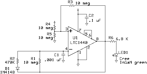
As shown, according to my testing, this circuit drives a green LED from 9 volts with total current draw of 39 microamps. With the LED disconnected, current draw is 3 microamps, which indicates average current through the LED is 36 microamps.
Instantaneous current through the LED was measured as being .9 milliamp. This indicates a duty cycle of ~4%. Using the circuit as shown, the pulse frequency is ~125 Hz.
The specific green LED used for testing here is Cree CP41B-GFS-CM0N0674. I achieved about 6-7 millicandela from this LED using this circuit as shown. There is an improved verseion of this LED, the Cree CP41B-GFS-CN0P0674, which I expect to achieve about 7-8 millicandela from this circuit as shown.
Your mileage will likely vary a little.
UPDATE 9/5/2015: The CP41B-GFS-CN0P0674 is now available, it is even more efficient than the Cree CP41B-GFS-CM0N0674, and I have some. However, the ones I got have micropower steady DC performance so good that one with pulsed current averaging 28 microamps (31 microamps including current used by the pulsing circuit) has its brightness matched with 40-42 microamps of steady DC current, according to my 9/5/2015 testing.
UPDATE 10/14/2024: Cree CP41B series LEDs have had manufacturing discontinued a few years ago. Other Cree green LEDs with high efficiency are available, for example ones offered here.
For usage at 5 volts, change R6 from 6.8K to 2.7K or 2.2K. For usage at 4.5 volts, change R6 to 1.8K. For usage at ~4-4.5 volts, change R6 to 1.5 K.
Average current can be decreased by decreasing the value of R2, such as to 330K or even 220K. However, efficiency of the circuit is likely to decrease by a few percent. But, results are likely to continue to be impressive.
For use of LEDs other than favorable green or blue InGaN ones, it is likely necessary to decrease the value of R6. Try to not make R6 less than 680 ohms at 9-15V, or 470 ohms at 6.2-7.5V, or 330 ohms for voltages 6 volts or less. Make sure you are using a good LED for the job so that you can use a higher value for R6.
C1 should be a non-electrolytic capacitor such as polymer film or ceramic. Ceramic versions of C1 should have tolerance no worse than +/- 10% and temperature characteristic either X7R or C0G / NP0.
Resistors should have tolerances +/- 5% or tighter.
D1 can be substituted with 1N914 or MMBD914.
Also suitable would be a variant of this ultra low
power LED flasher using a low power comparator IC, at DiscoverCircuits.
Please read my Copyright and authorship info.
Please read my Disclaimer.