Its output is at 10.6 um (10,600 nm) or mid-IR. This wavelength is about 10 to 30 times longer than the other lasers under discussion and often considered a source of a heat beam than a light beam. At this wavelength, normal glass and plastic optics are either too lossy or totally opaque so alternatives must be found both for the end-mirrors and any other mirrors, lenses, or prisms required by the external optical setup. Divergence/diffraction effects are also increased by this same factor so obtaining a collimated beam is also more difficult.
Many common materials including wood, paper, plastics, composites, and properly prepared metal surfaces absorb quite well at this wavelength so the CO2 laser makes an effective marking, cutting, welding, and heat treating tool.
See the chapter: Carbon Dioxide Lasers for more information on the characteristics and applications of these devices.
It is possible for an amateur to construct a working axial flow CO2 laser (non-sealed, see the chapter: Carbon Dioxide Lasers) in the 10 to 50 W range without too much difficulty - at least compared to some of the other types of lasers described in this chapter. A vacuum system is needed but the range of operating vacuum is modest - 10 to 100 Torr. And while several gases are needed, the purity of the final gas fill isn't nearly as critical as for, say, the HeNe laser, and pre-mixed gas is readily available. See the section: More on Obtaining Gases.
With a bit of resourcefulness, no fancy glass work is needed. The power supply can be just a neon sign transformer on a Variac. The required mechanical precision isn't as great either so even if your machining skills are quite limited, adequate mirror mounts and structural components can be fabricated relatively easily. And, unlike the other traditional gas lasers (HeNe, Ar/Kr ion, HeHg, CuCl/CuBr, and the like), once constructed and aligned, the CO2 laser requires minimal maintenance and can potentially be a useful tool for real applications IFF it is packaged appropriately and provided with essential safety interlocks and protection devices. In fact, some commercial axial flow CO2 lasers are just refined versions of what an amateur can build. See the section: Descriptions of Typical Small Flowing Gas CO2 Lasers.
My only complaint about CO2 lasers in general are that the beam is totally invisible and boring in some ways. :-) Otherwise, it is nearly the perfect choice for a home-built laser - high power, continuous operation, and relative simplicity!
Although, constructing a CO2 laser is easy relative to other types of lasers, it is still NOT easy in an absolute sense. You will have to make a very considerable commitment of time and effort including dealing with the frustrations when, as is inevitable, some things don't quite go according to the script! The costs in $$$ can quickly become significant as well if you don't already have any of the supporting equipment (e.g., vacuum pump, power supply components) and aren't a first rate scrounger. :)
If all you want is a reliable working laser, save your money and buy a used CO2 laser system. Something similar to what you will be building can probably be acquired for under $1,000, perhaps less depending on your resourcefulness and luck. For example, see the section: How to Get a Laser Without Really Trying - Part 1. If you can afford a bit more, try to find a sealed tube CO2 laser system. These have essentially zero maintenance, and no requirements for a gas supply or vacuum system. New systems in the 25 W range can be had for around $5,000 from companies like Parallax Technologies. This is certainly not cheap but may be in the ball park once all your costs and time are factored into the equation. However, note that in either case, there could still be considerable costs associated with the beam delivery system for your application. For example, focusing lenses to get power to that wood stock can easily run an additional several hundred dollars.
You may easily spend hundreds of hours in constructing a working CO2 laser - especially if it is your first home-built laser. Note that while this estimate may seem high, it doesn't only include the actual fabrication of the laser head itself (tube, mirror mounts, and frame) but the effort required to select, acquire, and set up the vacuum system, gas supply and metering system, power supply and possible added branch circuit(s) to handle the electrical load, cooling system, and support structure (stable table or frame). And, providing and preparing the physical space: The home-built CO2 laser is not likely to be in any way portable and the kitchen table does not make a good work area. :) Once everything is put together, all the leaks are plugged, the parts that got trashed in shipping are replaced, you will have to align the mirrors (best done with a helium-neon laser - another expensive if you don't own one already), start feeding gases, apply power, and hope everything holds together!
Even after you achieve 'first light' (or I suppose, more correctly, 'first IR'), you will then spend countless more hours in getting the laser to be a reliable system - and it is quite conceivable that this goal may forever be elusive. If your heart isn't in the laser construction aspects of this endeavor, you will get discouraged very quickly.
If you DO decide to build your own CO2 laser, don't shoot for the stars, at least not at first. Begin with a modest size tube of say, 2 feet in length, which should still be good for perhaps 20 or 30 watts. There won't be any problems powering it with a 12 to 15 kV neon sign transformer and it will be small enough to easily fabricate - and store! Once you have gotten that operational, you will have solved all the tricky problems of vacuum, gas supply, mirror mounts, and cooling. It is easy to scale up something that works. However, starting with grandiose plans that fizzle will just lead to a box full of parts and equipment gathering dust in the attic.... :-(
(From: Flavio Spedalieri (fspedalieri@nightlase.com.au).)
Just to keep the expectations down, and also re-capping on the reason why we are building lasers in the first place.
For those who are building lasers for use as a tool, e.g., for metal or wood cutting, please be aware that you will be introducing a number of factors that will make it difficult for the final application.
Lasers for cutting applications should be producing a considerable amounts of power (around 100 Watts and up) to achieve a nice clean cut. At lower powers, it will take longer for the laser to cut the material, either if thin metal and or wood, and will cause burning and/or bad cuts. Another reason for having output powers in this range, is that at this wavelength, materials will behave differently (in terms of light behaviour) certain materials will reflect the IR energy, thus you are loosing energy through partial reflections.
Cutting lasers generally have to be very rouged, so to be resistant to fibrations that can cause mis-alignment of the optics.
Commercial CO2 lasers, are built so to be quite resistant to environmental changes. Also, many of the controls like vacuum, voltage/current, gas pressures/mixtures are electronically controlled.
For cutting applications, the laser beam must also be directed to the work piece, and this is done through an articulated arm - an optical waveguide. At the end of the arm, is the objective lens. These optics require to be enhanced for higher power IR beams, also it's not very easy at all, nor that trivial to build an articulated arm from scratch - much alignment involved.
Please be aware, that home built lasers are much more sensitive to vibrations, and are not of the 'plug-in and leave' variety. Home built lasers require much TLC, adjustments and continual tweeking, plus there is other things that have to be taken into consideration like: gas supply, mixture and gas pressure; power supply; mirror/tube adjustments and mounts; and thermal expansion and stability of the overall laser assembly.
Take precautions to avoid exposure to the direct or reflected beam. Since it is invisible, this means clearly labeling where it is and enclosing these in materials opaque to 10.6 um IR (these include glass and most plastics so it isn't that hard and doesn't obscure the action. Just because you can't see it, don't assume there is nothing there!
If you are using water cooling - either tap water or a closed loop system, make sure that water circulation paths are well insulated from the high voltage and that all fittings are securely grounded. Tap water is a fairly good conductor of electricity - think of it as a very soft wire. :) Unless you have a totally closed system filled with 100 percent distilled de-ionized water, there can be enough current flow to be lethal. Water and electricity do not mix!
(From: Chris Chagaris (pyro@grolen.com).)
Zinc selenide is an extremely toxic substance by ingestion and/or inhalation of dust, with a cumulative effect. This of course could be brought about if the optic were cracked or damaged in one's presence. This material liberates highly toxic hydrogen selenide in contact with gastric juices. Because of the material's reactivity with acids, it should NEVER be cleaned with even a weak acid, as these highly toxic H2Se vapors may be formed. Dermatitis may result from prolonged contact - don't play with your output couplers. :-) Although this material is practically insoluble in water, the use of gloves while handling the material is recommended. Gloves or finger cots should naturally be worn when handling any precision optic, as mentioned above. Particular care must be exercised when machining and creating dust or particles, not that I would think anyone will be machining their precious output coupler. :-) Symptoms of ingestion include garlic odor on breath. Ye best friend should tell thee. :-)
For more information, see the chapter: Laser Safety and the more specific information in the section: CO2 Laser Safety. Sample safety labels which can be edited for this laser can be found in the section: Laser Safety Labels and Signs.
(There may also be another book by the same author called just "CO2 Lasers" with more design information or it may be the same book.)
(From: Michael Andrus (andrus@ccountry.net).)
The summary below is for the CO2 laser from "Light and its Uses". Also see the section: Iannini CO2 Laser Description.
Refer to Typical Home-Built Carbon Dioxide Laser Assembly for a simplified diagram of the overall glasswork and power supply electronics.
CO2 can be easily obtained from dry ice; N2 from filtered air (despite the presence of O2 and other trace gases) apparently works well enough.
Unless you have your heart set on experimenting with various gas ratios or other gases, the use of commercial CO2 laser mix really is the best way to go as it eliminates the hassle and expense of a fancy gas mixing/metering manifold and the three separate sources of gases. CO2 laser mix is readily available from gas suppliers. See the section: Sources of Special Parts and Supplies for the Home-Built CO2 Laser.
Estimated gas consumption is roughly .1 liter/hour of helium per watt of output power. The amount of the N2 and CO2 then scales with their fill ratio. All of these flow rates are referenced to standard temperature and pressure (20 °C, 1 atmosphere). So, a 50 W CO2 laser will require roughly 0.625 liter/hour of CO2, 1.25 l/hr of N2, and 5.0 l/hr of He assuming the 1:2:8 gas fill ratios - or about 6.875 l/hr of CO2 laser mix. These gas flow rates don't sound like much until you realize that they will be almost 200 times greater at 4 Torr but of course the gas usage is still that relatively low number! :)
The idea isn't to pump CO2 laser mix through the tube fast as possible but to maintain a controllable pressure inside the tube with a slow flow rate. The gas doesn't get "used up" that quickly by the laser. Think of the pressure reguator and vacuum pump as an ideal voltage sources with the gas pressure regulator, tube, and metering valves as resistors. There should be a constant flow (current) through the tube and nearly constant voltage (pressure) across the tube. Thus, the resistance of the tube should be low compared with that of the rest of the system.
                Pressure     Supply      Laser   Vacuum      Vacuum
  Gas Supply => Regulator => Metering => Tube => Metering => Pump ==> Exhaust
                             Valve               Valve

                       V1 o---/\/\-------/\/\------/\/\---o V2
                               R1         R2        R3
                                                         D1
         H o--------+ T1                T2   +--------+--|>|--+---o HV+
                     )||               ||=||(         |       |
              Variac )<--------------+ || ||(         |  D2   |
              0-115V )||              )|| ||(      +--|--|>|--+
                 15A )||    Neon Sign )|| ||(      |  |
                     )||  Transformer )|| || +--+  |  |
                 +--+      12kV,100mA )|| ||(   |  |  |  D3
                 |                    )|| ||(   |  |  +--|<|--+
         N o-----+-------------------+ || ||(   |  |          |
                                       ||=||(   |  |     D4   |
                                       |   | +--|--+-----|<|--+---o HV-
                                       |   |    |
         G o---------------------------+---+----+
                                               _|_
                                              ////
The laser can be operated on half-wave rectified DC with about half the output power making for a very simple power supply. It can also be operated on the raw output of the neon sign transformer (AC) but the efficiency and maximum power output may be lower (though it isn't entirely clear why this should be the case since the discharge current is varying in the same manner for both cases). Even a low current oil burner ignition transformer (typically 8 to 10 kV at 15 to 20 mA) or smaller neon sign transformer will be adequate for testing of shorter tubes.
With the addition of some filtering and a ballast resistance to a basic rectified DC power supply, the nearly optimal current could be maintained continuously boosting efficiency and power output. To achieve a stable discharge, a ballast resistor of 100K or more will be needed. Based on its resistance and the tube current, the power disspation will likely need to be 100 W or more. A series/parallel combination of lower value lower wattage resistors will be the best option for its construction. A more sophisticated alternative to the huge ballast resistor is a regulator but doing this in the HV output would present some significant challenges, to say the least. :) Most modern CO2 laser DC power supplies are switchmode high frequency inverters using pulse width modulation to implement the regulation circuitry.
Once a filtered DC supply is used, a starter like a high power version of that used for modern HeNe laser tubes will be required. See the HeNe power supply information in the sections beginning with: Starters - Voltage Multiplier, Pulse, Inverter, Piezo.
Also, see the sections starting with: Power Supply Components for additional comments relating to the electrical characteristics of CO2 lasers.
Many variations are possible to this basic design beyond improving the power supply. These include changes to the resonator diameter and length; the addition and/or substitution of other gases, ratios, and pressures; and better optics. With the relatively non-critical vacuum requirements ease of mirror alignment, making these sorts of modifications should be fairly painless.
However, don't go overboard - at least not on your first attempt. Keep it relatively small, simple, and get it to work! Once you have a functioning CO2 laser, it will be relatively easy to scale it up. However, as the tube length is increased, the power supply voltage may need to be boosted as well. A 15 kV neon sign transformer may not be able to power a 1 meter discharge tube (around 0.8 meter appears to be the limit) reliably over the pressure range required for CO2 laser operation. If you are really interested in higher power lasers, consider a design using a split discharge tube. See the section: Steve's Notes on Boosting CO2 Laser Power and Quality Construction.
(From: Steve Hardy (hardy@sweng.stortek.com).)
"CO2 lasers operate at low temperature, so even soda glass could be used. Most people opt for borosilicate, since it's quite cheap and has better heat resistance (less thermal expansion). A quick back-of-the-envelope calculation shows that the temperature on the inside of a typical axial flow CO2 laser is only 20 °C above the cooling water temperature. Nevertheless, there may be hot spots (e.g., at the ends) which may be enough to crack soda glass.Regarding other materials (notably plastic), these could be used but have the disadvantage of lower thermal conductivity, lower stiffness, and higher price than glass. Fused quartz, alumina or beryllium oxide could be used, but the performance gain would not be worth the enormous expense."
Many people ask about where to get the bellows used to join the mirror mounts to the discharge tube. While, these are available from various industrial supply and optics companies, they will be expensive. However, there are a variety of low-tech alternatives including flexible water or natural gas line - readily available and low cost at your corner hardware store or home center. To be reasonably flexible, these may have to be longer than a real bellows, but then your mirrors will be further away from the bulk of the discharge and less likely to suffer from sputtering damage!
(From: Michael Andrus (andrus@ccountry.net).)
"For the bellows, I used pieces of flexable metal gas line. You can get this at a hardware store for a few dollars as opossed to $40 each for real bellows. This avoids the alignment problems with an O-ring-only design."
Try Janos Technologies for inexpensive but good CO2 optics and professional design help. Other sources for CO2 laser optics include II-VI Incorporated and Design Research Optics.
For external (e.g., beam steering) mirrors, I've even heard that the platters from harddrives work well, at least at low to medium power. While these are usually very slightly textured to minimize stiction, since the CO2 laser wavelength is over 10 times longer than visible, this is likely not a serious issue and doesn't produce much scatter. However, this should be confirmed for the specific platters being used.
(From: Flavio Spedalieri (fspedalieri@nightlase.com.au).)
I purchased my mirrors from Design Research Optics, 1-401-885-7353, Contact: Bruce Sunderland:
  Part #                Description                                 Price
 ---------------------------------------------------------------------------
  2-Z-80                Zinc Selenide output coupler                $100.00
                         1.000" Dia x 0.120" Thick

  TRCC-1012-S-10-ES     Silicon Total Reflector                     $ 80.00
                         Enhanced Silver, 1.000" Diam.
                         x 0.120" Thick, 10 m radius.
Meredith Instruments current (March, 1999) has some CO2 optics at very reasonable prices ($49 each for ZnSe HR and OC, ZnSe lens, and silicon mirror). Check out their Miscellaneous Laser Parts page.
(From: Sam.)
Here's another company that lists CO2 laser optics but they probably aren't cheap: Laser Research Optics.
The following may also be useful though I don't know if he has anything other than lenses (e.g., mirrors) or smaller quantity pricing but it won't hurt to ask:
(From: Mubashir Khan (MubashirAK@aol.com).)
I would like to offer my services for such people who need inexpensive ZnSe optics. My manufacturer can produce such components in small quantities also. This offer is primarily for amateurs and hobbiests but others can also benefit. As an example, I have ZnSe plano-convex and plano-concave lenses starting at US$55/piece for 5 pieces. For more detail I can be contacted via email. I am with MnA Optiks, Postfach 1224, 64560 Riedstadt, Germany. Phone: +49 6158 915696, Fax: +49 40 3603 763573.
(From: 3jl (jjjimenez@terra.es).)
The construction of a mirror for a laser is not an easy work.
So, commercial mirrors are made of gold with several layers of ZnSe and NaF (or BaF) via sputtering, and have a reflectance greater than 99.5%. The problem is the cost.
I have been able to solve those problems buying the mirrors in Ebay. Make a search with "CO2 LASER". You could get a surprise.
For operation on DC, a bridge or full wave rectifier can be constructed from microwave oven HV diodes (typically 12 to 15 KPRV, .5 A). Depending on the output of your transformer, either 1 or 2 will be required in series for each rectifier (1.414 * VRMS minimum PRV). If you get them from the same lot number, equalizing components are probably not needed where 2 are in series. Electronics service parts places like MCM Electronics and Dalbani usually sell replacement diodes for about $2 each. If course if you want to construct your own, a stack of 1N4007s will be even cheaper. See the section: Standard and Custom HV Rectifiers for more information.
In addition, if you want to drive your tube with filtered DC, smoothing capacitors as well as high power ballast resistors will be needed. Electronics distributors or electronics surplus outfits are the most likely source for these. Of course, you could get really fancy and add a current regulator. There is some discussion of this in the chapter: Carbon Dioxide Lasers and some circuits that may be useful as a starting point can be found in the chapter: HeNe Laser Power Supply Design. However, these are for the advanced course. :)
Note that if the coolant comes in contact with the electrodes, it needs to be non-conductive. Distilled water may be acceptable. Mineral oil is an excellent insulator (if kept dry) as well and often used for cooling transformers and other electrical equipment but is flammable. However, it isn't perfect:
(From: John De Armond (johngd@bellsouth.net).)
Disadvantages of mineral oil: Lower heat capacity than water, a bit harder to pump, flammable, softens some polymers, it is conductive when contaminated with moisture, may polymerize under the influence of UV from the discharge tube, especially if there are any paraffinic fractions in the oil, doesn't magically dry up when you kick a can of it over. :-) I'd certainly use transformer oil if I went that route but you still need to keep it dry.
For a circulating pump, it's hard to beat a carbonator pump. Around here, the used restaurant equipment places practically give them away. Coke will put fountains in restaurants and then when the restaurant goes out of business, they'll either not get the fountain at all or else they'll just get the head and leave the rest. In any event, carbonators are running out the yingyang around here. They usually come complete with a 1 gal stainless steel tank.
The little submersible pumps lack the head pressure you need to force a meaningful flow through tubing. These things are typically rated for only 20 feet of head or so and that is only a few PSI. The pump will churn and froth and look like it's working but it's not. you really need a positive displacement pump. If you can't find a carbonator pump, another option is the peristaltic pump. This is the familiar "roller and rubber tubing" metering pump. These things are cheap enough to be throw-aways. Indeed, I've had several different vendors in my restaurant for grease cutting enzyme drain treatment. Each vendor installs a peristaltic pump to meter the enzyme. And when they let the reservoir get empty and I fire 'em for not servicing it, they never bother to come get the pump. I have several on the shelf. What's really nice about these pumps is tubing can be had for almost any media. Silicone rubber is typically used but if you want to pump something really gnarly, any tubing that is reasonably flexible will work.
(From: Steve Roberts (osteven@akrobiz.com).)
The 25 to 50 W Sharplan lasers use a 22 litre per minute plastic pump made in Germany by a company called Eheim (model 1060). It's got a nonconductive case and rotor but is not self priming. They have a 1 liter reservoir above the pump to keep a constant level in the system. The radiator used is a 6" by 8" unit with 3 layers of fins, 1/4" tubing in the core, and a 200 cfm fan.
(From: John De Armond (johngd@bellsouth.net).)
Check the restaurant supply outfits near you. Just like the carbonator pumps, CO2 regulators regularly get tossed when the old fountain gets yanked. A couple of years ago I walked in one of my favorite used restaurant equipment places and found a large box of regulators labeled to go to the brass scrap yard. I bought half a dozen for their scrap value. (No, don't want to sell any. :-( $5 is the maximum I'd pay for one. Change the CGA nipple and away we go.
For a fairly cheap ($20 to $35) flow meter, check out either your local welding equipment supplier or companies like OMEGA Engineering, Inc..
The use of premixed gas also doesn't allow you to easily experiment with changing gases or the partial pressures of each gas. The obvious way around this is to provide separate tanks for each possible gas and a mixing manifold. Needless to say, the costs, complexity, and difficulties in controlling and monitoring gas flow can quickly get way out of hand.
If you really don't want to invest in official CO2 laser mix or high pressure tanks, regulators, gauges, and metering valves, there are alternatives, at least to get your laser going initially: CO2 from a chemical reaction (e.g., vinegar and baking soda!), CO2 cartridges, or seltzer makers; nitrogen from the air, and helium from party balloon tanks. Depending on what you end up with, gas composition and purity may be somewhat hit or miss, but CO2 lasers are fairly forgiving. As long as you use decent optics that are fairly well matched to your laser tube length, there is an excellent chance of getting the laser to work, though probably at much less than optical performance:
However, some companies may charge a lot for a single tank of CO2 laser mix:
(From: Curt Graber (cgraber@fwi.com).)
Sad to say but most of the larger corporate gas supply companies want to have a bottle a month relationship min. and if you sound like you have never leased/purchased a tank previously they automatically go into unobtanium mode and pricing.
doing your own mix is a great opportunity to tune your resonator for it's tastes in gas mix but will not save you any money at all as you need a significantly bigger manifold set-up and precision meters to correctly (read repeatably) set-up the mix as the gas is depleted from each reservoir at different working pressures and volumes.
My suggestion is to find a second hand medical laser supplier and buy a full or mostly full tank of pre-mix that was a "removed from medically obsolete" flowing gas laser, there are a lot of them out on the market! and the bottles typically get thrown gently on the shelf to await another lifetime and or lifestyle such as your application.
If you don't have any second hand medical equipment suppliers in your area scour the internet for a find close to home as you will want to likely also see their other wares stripped from similar units.
(Portions from: John De Armond (johngd@bellsouth.net).)
Generating the CO2 chemically could be kind of nasty unless you came up with some sort of drying scheme. Not only may water vapor interfere with lasing, the coating on some optics or the base material itself may be damaged by excessive moisture.
Why not use the CO2 cartridges for pellet guns or seltzer water bottles? You can buy a seltzer water maker at the local kitchen notions store for under $10. It'll puncture a CO2 cartridge and bleed it into a pint metal bottle. If you vacuum the bottle beforehand you'll end up with clean CO2 at a reasonable pressure.
Alternatively, I only pay $10 for a 20 pound tank of liquified CO2 from Coke for the fountain in my restaurant. That's high compared to what I could get it for if I owned the tank. Coke charges no rental and only a $30 deposit. If you have a favorite restaurant, perhaps you could get the owner to sell you a tank of CO2. Another possibility is a party shop. Party shops around here sell pony kegs of beer (about 1/3 the size of a regular keg) and loan the tapper (with a deposit) that consists of the fittings to the keg, the dispensing head and a small CO2 tank (about 3 pounds, I'd guestimate). Even if you have to buy the keg of beer, life could be worse! :-)
As for cheap helium, around here, Wal-Mart sells a party kit that contains a 30 pound Freon cylinder filled with He and some balloons for about $20. OK, so your really don't need the balloons. :) Some of the party stores carry it too but they charge more. Since it's a standard Freon tank, it has a standard SAE 1/4" flare refrigeration fitting. You can attach either a refrigeration service hose or simply a 1/4" flared copper tube. The tank is pressurized to about 275 pounds so there's quite a bit of helium in it and the helium is pretty pure. I use those tanks in my neon shop for helium flush gas on my pumping manifold. This is about the cheapest helium one can get, particularly when you figure in the lack of a cylinder rental (or purchase).
(From: Steve Roberts (osteven@akrobiz.com).)
A few suggestions:
I just gave away 2 medical surplus tanks at 3/4ths full to a local artist for his laser carving experiments as I'm not a CO2 person. I paid $50 a tank for one and the other was on the laser I scrapped. When my artist friend asked asked me what the refill cost was, I called a medical laser friend and he said, out the door cost with new tank and full tank ownership in St. Louis from his local gas supplier was $140 and tax. Now what he has is a local more independent gas company that buys bulk and blends their own mixes, instead of a big national chain. I'd find such a place, they do exist, go see em in person, not on the phone, present a reasonable appearance and if they ask you what partial pressures you think you need, be able to answer them. I bet you score a tank cheap.
Usually laser gas is considered a high purity mix and they need to vacuum out the tank, weigh it, specially clean it, then mass spectrometer certify it, etc. For a really precise lab laser or sealed service, I could see it needing that kind of preparation. But what my buddy does is have the local place do the mix on a normal fairly clean tank by pressure and percentages. They have no problems and the laser works just fine.
So I'd either talk to the biomed engineers at your local hospital or find a used Sharplan tank from a medical reseller or find a more reasonable gas place.
However, if you're mixing your own gases, for a flowing gas laser, normal 99.999% tank gas is fine. The people who tank the gas won't certify it as 99.999% but that's what it is, and usually better. A few parts per million of impurities won't hurt you. But, sealed off lasers are a whole different matter.
Unless you have a monster of a CO2 or are in daily production, the unit just sips gas, especially if you add the solenoid that kicks off the gas after the regulator when the plasma is off.
The local 5 kW CO2 job shop burns one big size S tank every four to eight hours. If somebody does laser cutting in town, hit em up for a tank at their rate plus a little extra. If you have one near by, they probably will help you out once or twice, as the more they buy the cheaper it gets! But watch out for demurrage charges, which is when a tank sits too long at one place.
Setting up a blending station at 1 to 10 Torr final pressures is a real pain in the neck, most needle valves, even the micrometer ones, are not that good, and I do high vacuum as part of my living. Just adjusting the final pressure needle valve on a flow gas is a dog. CO2s do lase over a broad pressure range. You can be both too low and too high and still get about 1/2 the rated power, but the sweet spot does vary some what with current.
I actually got some lasing once using a welding shielding argon/CO2 mix and blending in nitrogen, but 1.5 watts out of a 60 watt tube was kind of disappointing. :-)
(From: Tom Miller (tmiller@umaryland.edu).)
I picked up one of the He tanks from Wal-Mart today - $15.19 including tax. This tank is the size of the 15 pound freon tanks usually found in automotive shops. I think if we used these by adding a small amount of co2, only 4 to 5% more pressure, and bleeding air in for the N2/O2, it should make for a cheap setup.
(From: Sarlock T. Icedragon (sarlock@twcny.rr.com).)
I checked a local company out here and they will sell me a 20 pound CO2 tank, and the first fill with custom mix is on them (if the tank is bought from them of course). For this they ask a total of $117.
(From: John De Armond (johngd@bellsouth.net).)
That sounds like a pretty good price if he's actually selling you a new tank. Particularly if it is an aluminum one. (Luxor is the most popular brand of aluminum tank.)
Here are some additional comments on CO2 gas mix.
A gas filling station cannot legally fill a tank owned by a competitor. Many gas companies will "sell" (actually a one-time charge) you a tank. The tank will have their name on the collar and they take the empty and give you a full one each time. As is obvious, after the first filling, you no longer possess the same serial numbered tank as is listed on your "purchase" receipt. There is no problem until you take that tank and try to get it refilled at a competitor's station. When the competitor sees another company's neck ring on the tank and the tank serial number does not match the receipt you bring along, they typically refuse to fill it. Or if they do, they will not do a tank exchange and instead send your tank off for filling. That means you have to wait for it to be filled.
If you actually buy the tank, the neck ring will be blank. You can stamp your name on it if you wish. Your tank's serial number will match the one on your sales receipt. Your tank will be sent to to the specialty gas supplier of your choice, filled and returned.
All that is required to get any tank filled is (1) proof of ownership (sales receipt does just fine) and (2) current hydro (date is stamped on the cylinder). Since laser gas is a specialty gas, one won't be buying it from the local welding supply store so the issue of swapping an empty tank for a full one versus sending the customer-owned tank off for filling doesn't arise.
You don't need a fancy expensive regulator. A MIG gas regulator is less than $50 at Tractor Supply and other outfits that sell the Century welder and all of its private label versions. A helium balloon filler is even cheaper. CO2 laser gas is lo-tech, unlike some other types of lasers that require very pure gas.
As for shipping, if you have to UPS it, put it in a box, label it as compressed gas and ship. UPS charges a hazardous materials surcharge because it is high pressure (and because they can).
(From: Steve Hardy hardy@sweng.stortek.com).)
The typical ratio of 1:2:8 of CO2, N2 and He respectively was suggested by Linde Gas who supplied my mix. The precise ratio is 9:18:73, and is expressed in terms of partial pressure. In practice, this is fairly close to the molar ratio (since most gases at 1 atm and 20 deg C, are about 1 mole per 22.4 litres).
Please don't worry about precision. 10% deviation either way in any of the components is not going to make a noticeable difference - at least not to us amateurs.
You may hear of different ratios being used in various circumstances - usually the amount of He is varied. For example, a lower ratio of He is used in a TEA CO2 laser. You can even run your laser with 1:1 CO2:N2 and no He, with reduced efficiency.
(From: Sam.)
See Spectra Gases' CO2 Laser Mixtures Page for some typical percentages.
(From: Mark Dinsmore (tango@coolmail.net).)
I found what might be another source for CO2. We have a local paintball supplies store, and I bought a 12 ounce bottle of CO2 and valve, full, for about $40. 12 ounces of CO2 is a LOT of gas, and a refill is only $2.00. I saw the guy fill it from a standard full size siphon tank, so I believe that it is reasonably pure. I'm sure it's not research grade, but I'm hoping it's good enough.
Mirrors salvaged from commercial CO2 lasers will be satisfactory if their RoC and reflectivities are compatible with your tube length and they are in good condition. (CO2 mirrors are subject to both degradation during use due to high photon flux and from moisture/water damage while in storage.)
Although generally similar to the CO2 laser from "Light and its Uses" (see the section: Home-Built CO2 Laser Description, it is more than twice as long and should therefore be capable of much higher power operation. Some glass working is specified (though this could easily be avoided with minimal design changes) and the power supply has more frills (but is only AC instead of DC and therefore will not be as efficient).
This ultimate operating pressure of your CO2 laser depends somewhat on you final design. Long, small bore plasma tubes will effectively operate at higher pressures than shorter, fatter tubes. Long, relatively small bore CO2 laser tubes will operate at between 25 and 35 torr, at best.
The high pressure regulators normally attached to compressed gas cylinders will not offer the control needed to accurately 'feed' a CO2 laser. Needle valves must be incorporated in the lines after the regulators to adjust each separate gas flow to the laser head.
There are much simpler options available rather than using neon sign electrodes in this type of laser. Why do some people insist on neon sign electrodes when they are not really needed in a small slow-flow CO2 gas laser? If your laser is to be operated on DC then all you really need is a short length of copper or brass pipe in the plasma tube as a cathode and simply a small loop of wire as an anode.
There is a need for a massive electrode (copper pipe or similar) on the cathode-end of the tube, as electron/ion bombardment will tend to heat this end. The anode-end only requires a wire loop. I would leave the method of sealing the wire into the glass tube to those with glass-working skills, as there would be many ways to accomplish this.
As an experiment, I ran the CO2 laser using a 10,000 VDC, 30 mA power supply. Ambient temperature was 77 °F. The cooling water for the plasma tube started at 76 °F, as I had not kept my chiller plugged in to power over the past several weeks. After approximately 45 minutes of normal operation the cathode electrode (the one we're concerned with) was just warm to the touch (be sure to turn off power for that test!) and measured just a tad over 100 °F according to my 'not very accurate at that low temperature' temperature sensor. Don't worry about this if you are using a good-sized electrode.
A three electrode configuration does have some merits, but only if you have a special power supply designed to properly operate this type of design. You would ideally want the anode in the center of the tube and cathodes on each end. The cathodes must be large enough to dissipate the heat created by ion bombardment while the anode can be much smaller, as this does not heat up and is better suited to be in the center of the tube. This set-up would not be practical using a neon sign transformer, as the secondary high voltage windings are center tapped to case ground. More importantly, is that you would not gain anything using a single NST. You would merely be putting half of the output voltage on each half of the plasma tube. Water jacket construction also becomes much more difficult when dealing with a center electrode type configuration.
The easiest and least expensive method for attaching the electrodes to the CO2 plasma tube, which will require no glasswork, is to use the copper pipe fittings at both ends. This will also allow those who wish to operate on AC a simple solution. The common copper pipe fittings that are available at your corner hardware store will work well in this application. With a little modification these will also provide ports for vacuum and laser gas. If you attach alligator clips to your power supply output wires, these can be attached anywhere on the copper fittings for simplicity.
My copper fittings are attached to the plasma tube using an O-ring seal and a simple clamping method built from Plexiglas plates and machine screws. Two-part Epoxy is employed to attach the first Plexiglas plate to the outside end of the plasma tube and to attach the end of the copper fitting to the second Plexiglas plate. All the screws are placed 120 degrees apart. Mirrors are Epoxied onto the mirror adjustment plates and a thick O-ring will provide both a vacuum seal and enough play for mirror adjustment (no bellows required). This is a very simple and inexpensive method which works well and should allow anyone with a reasonable amount of mechanical skills to build a functioning CO2 laser without the need for exotic or expensive equipment.
I use a standard CO2 laser gas mix of 4.5% CO2, 13.5% N2, and 82% He. This is commonly available from commercial suppliers like Airgas, Inc which is where I obtained mine. These companies can usually provide whatever mix ratios you specify. Other mixtures that I have seen that will reportedly work well are: 8:8:84, 4:28:68, and 15:25:60 (CO2:N2:He respectively). I would guess that experimentation with varying ratios would lead you to the best mix to use in your particular laser.
My original CO2 laser and power supply is pretty much along the lines as the Scientific American as described in the section: Home-Built CO2 Laser Description
I have recently built a smaller and more compact power supply for it. This consists of a 9,000 volt, 30 mA neon sign transformer, manufactured by the Canadian firm of Allanson, as the basic unit. This is the type of transformer with the two high voltage terminals coming directly out the top of the tar insulation, all enclosed in a somewhat larger metal case. This case left plenty of room for a bridge rectifier, key switch, fuse, 'on' light, milliammeter and a 3 amp Variac. A six foot 3-wire appliance cord with IEC input module and two 20 inch high voltage output leads, with color-coded alligator clips complete the package.
This power supply seems to perform as well as the 15,000 volt @ 60 mA unit that I had employed in the past with this modest sized laser. I no longer have a supply of commercial CO2 laser gas and have been using the 'three separate gas' system for some time now with good success. I have been using a commercial cylinder of compressed helium (useful for most other lasers also), nitrogen from the air (bubbled through water) and sublimating dry ice for the CO2 supply. I had bought a small supply of dry ice on Friday which lasted only until Saturday evening, due to its tendency to mysteriously disappear even when stored in an insulated cooler. Out of sheer curiosity today I decided to try a much more readily available source of carbon dioxide gas to operate this laser with. Searching through the cupboards I found some white vinegar and a small box of baking soda. Lo and behold, a small amount of this mixture in a flask produced a fine source of CO2. I was pleasantly surprised to open the needle valve from this flask to the laser and see a fine burn pattern appear on my thermal FAX paper target. No more dry ice! I just thought you may wish to pass this on to the amateur laser community. This really simplifies the gas problem for small CO2 lasers.
All small CO2 lasers such as this operate under similar conditions. The gas mix is pretty much standard for most slow-flow CO2 lasers and is usually 4.5% CO2: 13.5% N2: 82% He. This should be available pre-mixed from any large industrial gas supplier. As far as optimum operating pressue, this should be easy to determine experimentally. It will depend somewhat on the plasma tube dimensions, but will likely be somewhere between 5 and 25 torr. If you have an adjustable output power supply, you simply start at a the lowest pressure and lowest current setting that will allow laser output, then slowly increase pressure as you increase current. You will find that power output of the laser will increase to a point of saturation. Just below this point, at the highest output level, is where you want to set your controls
Being able to see the glow discharge through a clear glass tube has advantages beside the purely aesthetic value. With some experience operating a CO2 laser, one can tell much about the operating conditions from the visual appearance of the glow discharge. The color, intensity, and density of the plasma all give clues to adjusting parameters such as gas mix, gas pressure and current density for optimum performance and power output.
I am not sure of the power output I am getting with this system, but it will easily ignite the FAX paper in a matter of five to ten seconds without any focusing optics. The burn pattern is quite large also with this wide bore (1 inch) plasma tube. I have read about your plan for measuring CO2 output power by heating a measured quantity of water for ten minutes. I have yet to try this yet, basically for lack of a suitable reflector to steer this beam into a container. I have a simple thermometer with a flat black penny attached to the stem to see temperature rise from the beam impinging upon said target. This allows some comparison of output power, but is there anyway to translate this to watts? I am getting about a one and one half °C rise in temperature per second at full power.
(From: Sam.)
Yes, by knowing the mass of the penny (about 5 grams I think) and the rate of initial rise in temperature, you should be able to calculate the approximate beam power. What you need is temperature rise/joule (or calorie) of energy for a standard penny. :-) I say 'initial' since losses due to convection and radiation of the heat energy will be small. This is still going to be tricky without a serious effort to insulate the 'sensor'.
Here are some notes on the construction and power output of my home-built CO2 laser:
Plasma tube:
I do not recommend having a plasma tube of 1,000 mm (or more) in length, there my be problems with sustaining the discharge. 15/30 NST will not be enough in striking a tube of this size - even a 15/60 may have some troubles.
I have cut my tube length from 1,000 mm to 800 mm.
For my tube, I chose a bore size of 20 mm ID and 24 mm OD. The larger bore will generate more power.
Optic/mirror adjustment mounts:
Refer to the following absolutely fabulous ASCII drawing when reading the description below and also see Flavio's Carbon Dioxide Laser Plans for some details.
               _           _                       _           _
    HR        | |         | |    Resonator Rod    | |         | |       OC
 Adjusting  =[| |]=======[| |]===================[| |]=======[| |]=  Adjusting
   Screw  _   | |         | |     (One of 3)      | |  Out    | |   _  Screw
       O=| |=>| |   ______|_|_____________________|_|__||__   | |<=| |=O
       __|_/\/\_|__|_______________________________________|__|_/\/\_|__
      |   Bellows                 Plasma Tube                  Bellows  |
    HR|__ _    _ _______________________________________________________|OC
         | \/\/ |  |_  ____________________________________|  | \/\/ |
       O=|_|=>| | In ||   | |     Water Jacket    | |         | |<=|_|=O
              | |         | |                     | |         | |
            =[| |]=======[| |]===================[| |]=======[| |]=
              |_|         |_|                     |_|         |_|
My laser tube has an integral cooling jacket, and at both ends of the plasma
tube are 20 mm long extensions of the main plasma tube. These extensions then
go into two copper pipe fittings (one at each end. The solid fittings then
are soldered to a set of copper bellows, then another pipe fitting is soldered
to the other side of the bellow.
One end of the bellow assembly is connected to the plasma tube, and the other is soldered to a small brass plate. The brass plate then is screwed into a Plexiglas plate that forms part of the adjustment plate. Behind the adjustment plate (the plates closest to the center), are a set of fixed Plexiglas plates, these actually DO NOT support the plasma tube in anyway. In this plate, will be fastened a set of three fine threaded rods positioned in the typical 'L' configuration. The front adjustment plates are then spring loaded onto this plate - which enables the adjustment.
In the front adjustment plate, the front has been worked so that the optics sit in an 'O-Ring' groove, then a clamping plate is positioned over the optic to hold it in place - vac tight seal, and the ability to remove the optic and not mess up the alignment of the laser.
There are no requirements for specialized ceramic insulators required. And, best of all, the optics and their adjustments are isolated from the high voltage. But all caution must still be taken into account when working on the lase.
Estimated power output:
Although it is very difficult to determine due to the many variables involved, from my design using 1" optics, 20 mm bore, 800 mm length, and a power supply of 15 kV at 60 mA, I am guestimating an output from 20 watts up to 60 watts - but this is only a guestimate going on commercial lasers of similar size.
Providing more voltage/current will give you higher output, until you reach a saturation point where the output will begin to decrease with further input (the same as a HeNe laser).
(From: Steve.)
My laser was slightly unusual in that a filtered DC supply was used. This means I had the luxury of earthing the cathode and. If you use a neon sign transformer, you won't be able to do this - so please make allowances!
Tube Size:
I recommend the use of a smaller diameter tube. You can run them at higher pressure and higher current, since the smaller diameter provides better cooling of the gas. I used 15 mm ID tube, but only because of ignorance when building it. Nevertheless, I was very pleased with the results (about 30 W out for 600 W in).
Electrodes:
The electrodes do not get overly hot in operation. Most power is dissipated in the gas, which is largely conducted to the tube. The anode stays cool by normal convection. The cathode is subject to ion bombardment but this is not as bad as some people suppose, because the gas pressure is high enough that the mean free path is so short that ions don't have much chance to accelerate. Solder most definitely will not melt.
Aluminum is a good choice for electrodes. It naturally acquires an oxide film, which reduces the danger of sputtering. I examined my electrodes after operation and found them to be covered with an iridescent oxide film.
Vacuum stuff:
Laser gas is typically 1:2:8 ratio of CO2, N2 and He respectively. I have been assured by the experts at Linde that this is the only mixture you need to use for low flow lasers. This gas comes in steel cylinders, and has the trade name of 'lazpure' (at least for Linde in Australia).
The gas is compressed in a cylinder at many times atmospheric pressure. This has to be brought down to 25 Torr. You will need a regulator on the bottle. I happened to have an Oxy regulator which is just fine. The output of the regulator is adjustable between 1 and 4 atm. This is fed into the metering valve, which is basically an adjustable small orifice. I used a Porter metering valve (series 20) which costs under $100.
Metering valves don't necessarily cut off completely, so you need to be careful to shut the bottle off (using its valve) after use, to avoid damaging the tube or vacuum pump with overpressure.
The gas (quite cold due to its expansion from high pressure to a relative vacuum) flows rapidly down the tube to the anode end, where it is exhausted by the vacuum pump. Before exiting the tube, I have a slight restriction to slow the flow otherwise too much gas would be wasted. It would be handy to make this adjustable too (so you could control the pressure as well as the flow rate). If so, then make sure its gas conductivity is much, say 100 times, higher than the metering valve at the other end, because it is used at much lower pressure differential. One possibility which I haven't tried is to use a ball valve (normally used for water). Note that any parts which the operator needs to touch must be positively and securely earthed.
(From: John.)
There is a device available called the back-pressure regulator that makes regulating the pressure and flow much easier. A related device, the vacuum regulator will do the same job in this application. The back-pressure regulator works just the opposite of conventional regulators. It opens its port whatever amount is necessary to bleed off pressure in excess of the set-point pressure. With a back-pressure regulator between the vacuum pump and the tube, the tube pressure is with the regulator and only the flow rate is controlled by the inlet needle valve. This little valve will pay for itself in saved gas because with needle valves on both ports, one tends to juggle them until a stable pressure in the tube is achieved and then just live with the flow rate even if it is much too high.
(From: Steve.)
Sounds nifty. I presume the back-pressure regulator regulates the pressure differential across its inlet and outlet ports. Is there a type of regulator which can regulate to an absolute (but subatmospheric) pressure?
The reason I ask is that it would be nice to be able to set the tube pressure in absolute terms without worrying about the effect of the vacuum pump (since its inlet pressure would vary slightly with the flow rate).
(From: John.)
Two types are available. One type is referenced to atmosphere. The other has a vacuum capsule and is referenced to a vacuum and thus absolute pressure. Wallace & Tiernan (sp?) makes an absolute regulator but it is $$$$ new. I've seen 'em at C&H but not often.
(From: Steve.)
Note that with twin 'needle valves' I never had any trouble getting a stable pressure, but as you say it was hard to adjust flow rate and pressure independently. A regulator such as you mentioned would make life much easier.
(From: John.)
Yep. An alternative is the mass flow controller. A self-contained mass flowmeter and valve. Widely used in the semiconductor and thin film industries and so are fairly common on the surplus market. That way you set the flow with the controller and then set the pressure with the outlet valve.
(From: Steve.)
One problem would be actually measuring the flow rate. I thought of putting a balloon over the pump outlet, and measuring the increase in volume using Archimedes' principle etc. This would allow derivation of the flow rate in the tube by multiplying by the pressure ratio (atmospheric/tube). Or, just for fun, use a 'calibrated condom' and measure time-to-burst!
(From: John.)
:-) The common amateur scientist method is the soap bubble technique. This requires only a sidearm burette. A squeeze bulb is fitted to the burette and the gas flow is introduced to the side arm. Fill the bulb with a soapy water solution. When you're ready to measure the flow, simply squeeze the bulb until the water covers the side arm. A bubble will form in the burette. Simply time how long it takes to travel a set number of graduations. Assuming the graduations are in cubic centimeters, dividing the number of graduations transversed by the elapsed time in seconds gives the actual volumetric flow in cc/sec. This works best when the burette is vented to air. Assuming your vacuum system is fairly tight, you can flow the exhaust of your vacuum pump. This is especially practical if you're using a hermetic refrigeration compressor for the vacuum pump. Remember that the flow must be corrected to he tube pressure using the gas laws to get the flow through the tube.
A hot wire mass flowmeter is also very easy to make. Certain GM cars used a hot wire mass flow meter to measure intake air. If you find one of these in the junk yard, you'll see a small venturi containing a couple of hot wire filaments inside the flow path. Simply removing the integrated electronics from the housing and mounting the hot wires in a smaller tube is all that is necessary to make a very sensitive flowmeter. The integrated electronics output a pulse train whose frequency is proportional to flow. A computer interface is thus obvious. A cheap industrial pulse totalizer/rate meter can directly display the flow. The electronics require either 5 volts or raw 12 volts, depending on the model. Note that like all thermal instruments, the output is dependent not only on the flow but also on the conductivity of the gas so the instrument must be calibrated to the gas mix in use.
(From: Steve.)
The vacuum pump (and flow restrictor, if used) is connected to one end of a long tube. This tube must be longer than the discharge tube length to prevent arcing between the anode and the vacuum pump. The gas pressure in the connecting tube may be considerably lower than the discharge tube pressure, which tempts electricity to flow along it.
(From: John.)
Let me amplify on that a bit. If one plots voltage drop versus pressure, one finds that the minimum voltage drop, and therefore the longest possible discharge for a given voltage occurs at about 1.25 Torr. Below that it rises sharply until about 1 micron which is essentially a vacuum insulator. Above that point the voltage drop also rises but with a much more gradual slope.
To put this in perspective, a 15 kV transformer will run in excess of 100 feet of 25 mm tubing pumped to 5 Torr. The implication of this is that it is difficult to keep the discharge from following the vacuum line if the line is at a low pressure<. The solution is to put the discharge regulating valve near the vacuum pump so that the line from the laser is at the tube pressure. Then making the vacuum line smaller and longer than the laser tube will do the trick. Note that SMALLER tubing has MORE voltage drop. Since we're far from the molecular flow region, simple small tubing can be used. This is counter to intuition and conventional wisdom for vacuum systems where larger hoses are almost always desirable.
(From: Steve.)
This is interesting. However, I wonder (publicly) whether it is voltage drop which is the problem. I would have though that breakdown voltage is the key statistic.
As everyone knows, it takes a significant 'overvoltage' to start a gas discharge. Once the gas discharge starts, then the voltage decreases significantly depending on the available current (higher current may cause lower voltage drop; -ve resistance region).
This is why I wonder how you can talk about discharge lengths without specifying the available current.
Without actually trying this, I would have thought that a narrower tube would have a higher current density, and hence lower voltage drop. However, I will defer to your undoubted experience here.
The point I would like to make, is that we are trying to prevent dielectric breakdown in the gas column in the first place (not worrying about how it performs after it's been "lit") - this will be independent of the tube diameter.
It is also good practice to surround the vacuum tube with flexible PVC tubing. This is because some rubber tubes are slightly conductive (e.g. for anti-static properties) and often have a poor dielectric strength. I found this out to my cost when an arc punched a hole in my expensive vacuum line.
Now I use vacuum hose from the auto spare parts shop. The good stuff to get is used in trucks (part of their brake system or something). It's quite stiff, but seems to have better dielectric properties than 'proper' vacuum tube.
(From: John.)
This looks to be a place where cheaper is better. The (relatively speaking) cheap red gum rubber vacuum hose is completely non-conductive.
(From: Steve.)
Measuring pressure:
For measuring pressure, I made a closed end mercury manometer. Normally, filling the tube can be a real pain, but I found that a syringe is good for sucking up mercury. The mercury can be squirted into the manometer tube via some plastic tubing slipped over the syringe needle. I used insulator stripped off wire, however a recent visit to the hospital procured some tubing of the type which is used for epidurals. You can even get the filter section (which I needed, since my mercury had been much loved and was rather dirty). Actually, you can get some pretty neat stuff at a surgical supplier - scalpels, latex gloves, those nifty glass-in-glass syringes to name a few.
I have always had trouble manipulating Pyrex since I only have a bunsen burner. The bunsen can (just) manage to heat tubing so you can bend it. Anything more sophisticated is beyond its power. Thus the traditional technique of melting the end of the manometer closed was not available to me. Instead, I sealed it off with a plastic (acrylic) plug and epoxy. The other end connects to copper capillary. Mercury amalgamates with copper, but I think it will take a long time for the mercury vapour to create a problem. The advantage of the copper capillary is that it can be bent or crimped to create a restriction to air movement. You will appreciate this if your vacuum is suddenly lost - the mercury won't bash out the closed end of the manometer. Since mercury is nasty stuff, enclose the whole manometer in a mercury-proof container.
The first manometer I tried making used silicone diffusion pump oil, however this seems to have quite a strong surface tension against glass (the meniscus is concave as opposed to the convex mercury meniscus) to the point that it would refuse to separate from the end of the manometer. The oil seems to absorb gas and water, which requires that it be de-gassed by heating in vacuo.
(From: John.)
You might want to take a look at the DC-704 silicone fluid. It is much thinner than the DC-705 that many people use. It still sticks to the top of the manometer but a short blast with a heat gun or hand torch solves that problem. I like the expanded scale that the fluid (specific gravity about that of water) gives over mercury.
(From: Steve.)
Cooling:
I didn't want my laser to be tethered to the nearest cold water tap, so I decided to construct a recirculating coolant system. I found an excellent pump in the form of a bilge pump (used by boating enthusiasts). These run off 12 VDC and generate enough pressure head (centrifugally) to raise water from floor to table height. The cost is about $30. The 'tank' is a photography developing tray (11" x 14"), open to the air. The surface area is high enough to dissipate the waste heat.
Since I was paranoid about water leaking over the high voltage stuff, I overengineered the water jacket. It was made of aluminum tubing machined and then shrunk fit into end caps. The end caps included O-ring seals for the Pyrex tube to slip through. The cathode end was directly connected to the water jacket (and this is earthed for safety), so that maximum cooling would be available for the cathode (which tends to be the hot end). The anode was insulated from the water jacket assembly by 3 mm sheet acrylic, caulked in with silicone sealant. The laser assembly was actually supported by the water jacket, which is quite aesthetically pleasing (in my opinion).
Water circulates through the jacket, pumped by the bilge pump. I got fairly good at making hose barbs, since there is quite a lot of tubing by the time the whole thing is completed.
I used acrylic all over the place at the anode end. With the water cooling, there is very little heat.
Before you fly into a panic regarding heat dissipation, just remember that the dissipation per unit surface area of the tube is not all that high. My tube's waste heat is about 1 W per square cm. Just make sure there are no large areas (say over a few cm^2) which are covered by thermal insulators like plastic, otherwise a hot-spot will develop.
Don't put anything between the tube and the water since the thermal conductivity will be impaired. 2 mm thick glass will easily take 30 or 40 kV so don't worry about dielectric breakdown.
Don't worry about a short (say 3cm) section of uncooled tube at either end. Just let the air flow around it.
The purpose of the water jacket is not so much to get rid of vast quantities of heat; rather it is to keep the tube (and hence gas) temp as low as possible. (Sometimes I wonder if dry-ice/acetone would be an ideal coolant...)
Power supply:
You can never have too much power. If you have a choice of transformers, get the larger one! Throttle it back with a Variac. For twice the electrical power input, you will not necessarily double the output. It depends on so many factors. For the same setup, you may actually get more than double the output because the higher current may mean that you can increase the gas pressure, the tube gain, and hence the output coupler efficiency. Then again, you might get less than double the output if your setup is operating optimally at the 30 mA level.
My power supply is a 600 W microwave oven transformer, multiplied up to about 12kV. I found that at very low gas flow, the thing had about the power of a dead match (just enough power to smoulder a small spot on my much abused pine block). Opening the needle valve and simultaneously increasing the variac (to maintain about 70 mA) really boosted the power output (to the point of punching holes in the pine block). Unfortunately, further increases in gas pressure (and flow rate) caused the arc to go out since the power supply couldn't push the required current. A 15 kV/60 mA NST (900 W) should be good enough for pushing the performance envelope.
Measuring power output:
Everyone wants high power. It's very frustrating if you have no means of measuring the power output. I used the principle of measuring the equilibrium temperature of an object which absorbs the output beam. This is compared with the temperature obtained by the same object heated by a known resistance, when not illuminated. Although very slow to take a measurement, it is at least accurate enough to calibrate a faster instrument such as a pyroelectric or thermocouple detector. The 'object' is a finned aluminum block with a 15 degree conical hole. The hole is blackened by overheating olive oil in it. A 20 W wire-wound resistor is clamped to it (for the reference power source).
My new CO2 laser should produce about 500 W if I manage to solve a few problems.
I'm planning to use a folded tube. Currently, 6 tubes of about 600mm discharge length giving a total of 3.6m. These will fit into a 75mm diam cooling jacket. Both OC and TR will be at one end (the grounded end). The other end will be a fixed cube-corner arrangement, which means that only 3 flats will be required for a total of 6 reflections, and adjustment will not be required. Back at the OC end, 4 additional flats will be required for the beam folding. Pairs of these flats are combined into pre-adjusted cube-edge units, to minimize the required number of adjustments.
Although it is a lot of trouble to build a folded assembly, the shorter overall length (1m instead of 4m) will make the unit much more stable and useful. In addition, the increased cross-section and reduced length will allow the gas flow to be increased. Also, it's much easier to make a relatively low voltage supply (11 or 12 kV) to run the reduced length. Imagine the alternative of 40 or 50 kV for a 4 meter tube!
All this depends on the power supply, which is a major part of the whole project. I originally conceived this power supply as a versatile experimental aid. It operates from 240 VAC at 10 A or 415 VAC at 10A three-phase. The output is adjustable between 1 and 31 kHz (in 1 kHz steps), and the duty cycle adjustable between 0/256 and 255/256. The primary winding of the output transformer (a big ferrite core) is fixed at 50 turns, and the secondary is replaceable. I can put a single turn secondary for 12 V at 500 A (e.g. for welding) or 1,000 turns for 12 kV at 0.5 A (for CO2 lasers). The advantage of high frequency AC is that one can use much smaller capacitors and inductors. I am still in the process of designing this transformer, since the current version has too much leakage inductance.
Everything will be microprocessor controlled, so I can program things like pulse timings, feedback control, and so on.
I'm seriously toying with the idea of designing a more modest SMPS (perhaps 1 kW max output) specifically for laser experimenters. This would have the option of control via a standard parallel port. If I get this designed and working (hopefully in about 6 months), I might set up a kit for people interested in building it.
For the USA, would it be OK to design on the basis of 220 VAC being available, or is that inconvenient? It would complicate the design to be able to handle both 115 VAC and 230 VAC operation. Just dealing with 220/260VAC is much easier.
(From: Sam.)
Yes, single-phase 220 VAC (typically closer to 230 VAC) is usually available but would require running a separate outlet in most cases - no big deal. In the USA, 230 VAC is used for electric ranges/ovens, clothes dryers, larger air conditioners, and so forth.
However, it is a simple matter to operate on either 115 VAC or 230 VAC with a constant 300 to 320 VDC on the main filter capacitors - many SMPSs including large ones do this with a single jumper that converts between a bridge and a voltage doubler:
                        D1
          AC o-----+----|>|-------+---------+-----o DC (+)
                  ~|    D2        |+        |
                   +----|<|----+  |       +_|_
                        D3     |  |     C1 ---
                   +----|>|----|--+       - |
                   |    D4     |    +--o-o--+     +320 VDC to chopper
          AC o-----+----|<|----+ -  |  J1   |
                  ~|           |    |     +_|_
                   +-----------|----+   C2 ---
                               |          - |
                               +------------+-----o DC (-)
OK. I'll try to design with the option of filter caps. Without the caps, the voltage doubler trick isn't available so the driver will have to natively work with either voltage (115 or 230 VAC).
I'm expecting the price to be about $400 for the electronic and magnetic components, but this depends on how many takers there are. Typically, one has to order about 75 power semiconductor devices to get a discount.
I might downgrade the power output to 700 W if it makes a large price difference. After all, this is still a lot more power than your typical 15 kV/60 mA NSX (about 400 W).
Regarding DC output, this is an interesting question. There are basically three solutions:
There are other theoretical solutions, but not practical for such high voltages.
(1) suffers from the disadvantage of power loss in the ballast e.g. my laser required a minimum of 40k at 70mA i.e. power loss of 196W. The advantage is steady current which allows best _tube_ efficiency.
(2) Is electrically efficient, but tube output may be lower than it would be if driven by the same RMS DC.
(3) Would have the same performance as (2), but the cost of the rectifier is eliminated, and the power dissipated at the cathode is distributed over the two tube electrodes instead of concentrated on one end. This is an advantage as far as heat dissipation goes, but requires appropriate construction. Another possible advantage of (3) is easier tube starting, since the (HF) AC is going to ionize the gas by capacitive reactance.
The $M question is just how much difference in output is there between (1) and (2)/(3)? I don't know the answer, but I'm willing to bet that there would not be much difference if the operating frequency was over a few kHz. My guess is that the gas will still exhibit laser gain for a few tens of microsecs after the current drops to zero, thus at high enough frequencies the tube will respond more the the RMS current level rather than the instantaneous level. Please tell me if I'm wrong. If someone has the time, they should measure the output of their tube with respect to the 60Hz AC phase i.e. spin a strip of fax paper (wound around a drum spinning on a synchronous motor) and direct the beam onto it. If the fax paper is completely unaffected at one point it means that the power output drops to near zero at the current- crossing point.
Anyway, if I design this SMPS it will be a straight HF AC output -- you will have to make your own arrangements for rectifying and filtering. To minimize 50/60Hz modulation, the rated output will be obtainable for any input voltage over, say, 50 V with the duty cycle varying to keep constant output whenever the input AC is over 50V. This will provide 'steady' output for 80% of the time with 115 VAC input (or 91% at 240 VAC). The power factor won't be real good, and there's a few technical problems to overcome, so specification subject to change!
I'd like to report a successful power-up on my laser. Some photos of the laser can be found via the Lasergrowing 1 Web Page.
I lined the mirrors up very carefully with a little laser pointer and as soon as I turned on the current, it burned a perfect 1/2" round spot on some paper-covered plexiglass I was using for a target. I then graduated to a red brick, and got a nice round red hot spot the same size. When I put in the 7.5"FL lens I bought, things got really exciting. The brick got white hot when placed near the focal length, and the beam melted the brick to a diameter of around 0.2". This is a bit bigger crater than the 30 Watt CW YAG laser I have at work will do. I then switched to the 3" FL lens, and started playing with popsicle sticks. Waving the stick through the beam at the focal length made a really pleasant buzzing noise with a white hot spot on the surface, and would burn a line through half the stick in 100 milliseconds. I could tell the time because I could see the 120Hz pulse rate burned into the stick! If I moved the stick a little slower, it would slice it right in half. The only problem is that there is a strong jet of smoke directed right back at the lens, and it got it a little smokey. It cleaned right up with some lens paper, but I definitely would need some kind of air blast to protect the lens.
The laser would operate over a very wide range of gas pressure and current, so that part of firing up your laser will not be very critical. It ran fine from ~5Torr to the point where the plasma blinked out, with no huge variations in output. I don't have my peltier power meter set up yet so I couldn't measure the actual power out, but it was quite gratifying. The only disappointment was that the electrodes heat up more than I expected. I am using aluminum cylinders 1"dia by 4" long, and they get hot enough to be uncomfortable to touch after about 5 minutes of operation(Yes, the power was off and the power plug disconnected!). If I want to be able to run continuously, I will have to find a way of heat sinking them or forced air cooling them. I am using a very simple mounting system for the optics, just pushing them against an O-ring with the adjustable optics mount. There is more than enough movement allowed by the O-ring to align the cavity. The mount is mechanically referenced to a 2" diameter steel pipe, so small movements of the plasma tube should not affect the mirror alignment(we'll see). I designed the adjusters with ceramic standoff insulators, so the adjustment knobs are at ground(water pipe!!!) potential.
The cavity is about 1 meter, with a 5 meter radius total reflector, and a 80% transmission output coupler. I am using the gas mix recommended in the CORD information, i.e., 1:1.5:9.3 CO2:N:He at about 0.5 liter/min. I just mixed the gas using partial pressures in a small gas bottle. The He and N2 I got at work, ultrapure stuff, but the CO2 I got from the local paintball shop! The active length is 80 cm, with a 15 kV, 60 mA NSX powering the system with AC. I will try to get some pictures to post sometime in the near future.
I am intrigued by U.S. Patent #4,756,000: Discharge Driven Gold Catalyst with Application to a CO2 Laser where the gold is used to recombine decomposed CO2 in the laser. I notice on my 80 cm, 30 mA tube that the last third of the discharge region is turning whit-ish, a sign of significant contamination according to the patent. This happens even at fairly high flow rates (e.g., 4 L/min). I can think of several ways to get the gold on the tube, but before I spend any time on this I would like to know if any practical systems, i.e., commercial, use catalyst systems like this.
I've been burning other interesting substances (all in the name of science, of course!) I have a piece of alumina insulation, and the focussed beam generates a brilliant white spot and leaves a glazed trail on the surface - that's over 2000 °C, according to the books! I can burn nice round holes through mica. I still haven't attempted burning metal, other that a piece of stainless wire that I just got red hot.
I'm still not satisfied with the stability of my mirror mounts. I have to tweak them often to keep the max power up. I'm trying to analyze whether that is an intrinsic quality of using O-rings for the compliant part of the mount, or if it is sloppiness in the adjustable part of the mount.
In the middle of 1999 I built a small CO2 laser. This construction was similar to the Robert Iannini laser capable of 20 to 30 W.
One month ago I built a bigger and revised slow-flow CO2 laser. Here are some of the main construction details:
At this point any help or idea is welcome. As you can understand, there are no filter capacitor in the above PSU. I would appreciate if someone tell me where I can find 1 uF, 25 kV or something similar inexpensive oil filled capacitor for this function. I have in mind some place to buy such capacitor, but the price is prohibitive for me.
     +-----------+  +----+     +-------------------+   +----+  +----+  +---+
     | Vac Pump  |<-| SV |-+-<-|    Laser Tubes    |-<-| NV |<-| SV |<-|REG|
     +-----------+  +----+ |   +-------------------+   +----+  +----+  +---+
           |          |    v                                      |      |
           +----->----+    |                                      |      +-|
           |             +---+       +---------+                  |     / \
           |             |VS |--->---| Control |--------->--------+    |   |
           |             +---+       +----+----+                       |Gas|
           |                              |                            |Tnk|
           +---------------<--------------+                            |   |
                                                                       +---+
Where: REG = Regulator, NV = Needle Valve, SV = Shutoff Valve, and
VS = Vacuum Sensor.
Because I do not have a proper power meter yet, I'm not sure about the power output I'm getting with this system, but I estimate about 93 W, based on the CORD LEOT's equations for hemispherical slow-flow cavity. In the near future I'll buy a power meter from Macken Instruments. This laser is capable of burning holes in ceramics, plastics, and glass but I have not tried sheet metal yet.
I plan to automate the gas support system with electronically controlled solenoid shutoff valves, so when the vacuum falls below of 0.5 Torr the shut-off valves will open and the gas-mix feed the system with desire pressure. When pump stops, the valves will close, protecting the cavity from overpressure.
Details on my CO2 laser can be found at: Emission Technologies, Rob's company founded to sell CO2 laser plans, kits, and even a complete CNC laser cutting system.
What I wanted to accomplish was to build a CO2 that would be light weight, extremely stable, and powerful enough to do something with. My intent is to build a computer cutting table from scratch including the software which I will write in Borland Delphi 4. This tube puts out over 30 watts (and I have also built a similar 60 watt version.
The current design of the laser head itself is very stable and I am pleased with its performance. You can run it for 0.1 second bursts for drilling, or leave it on for twelve hours at a time. I figured hey, the commercial heads are mostly all glass looking like an overgrown HeNe, so why can't a home built tube use "glass only"as the structural member of the laser. I just used low expansion Pyrex with a relatively thick wall.
As for the machinist part, I have been tinkering for 20 years machining things here and there so I have basically taught myself. This tube was built in about three evenings of sitting at the lathe. Then a couple more nights spent re-machining parts to get the bugs worked out with an isolation issue. The mirror cells are stone cold electrically and this tube is safe to touch, adjust, or hold while running. This was another design parameter.
The cost depends on your stock of raw materials for machining, and your resourcefulness with the other components. The mirrors are the biggest expense for the tube at $50 for the HR, and $150 for the OC. The large Pyrex tubing comes in 48" lengths for about $40. The bore tube is neon sign tubing and can be had locally for $5 per 48" section. Teflon stock is pretty expensive though at $125 for a 2" by 12" piece of bar stock. I probably have $325 invested in the tube. The vacuum pump is a SPEEDIVAC manufactured by Edwards High Vacuum Ltd. in England. They cost about $2,000 new but I lucked out and got this one surplus in new condition for $300. The manometer is hand made from a 1 mm ID glass capillary tube and reservoir of mercury procured from several mercury switches. The gas flow gauge and needle valve are surplus and were cheap. Gas bottle - $125 new from welding supply plus about $30 to fill it with the laser mix. Gas bottle regulator - any inert gas regulator adjustable from 0 to 20 psi will do and they cost about $120 new.
In doing the math and assuming the use of a 40 cubic foot Bottle of gas mix (8" diameter x 18" tall), you should get about 18.9 Hours usage at 1 L/minute flow rate. The cost to re-fill the bottle is around $25.00.
The coolant system consists of 1 gallon tank with $18 bait well pump (700 gph) from Wal-Mart boat section running from a 12 VDC supply, and a copper heater core from a GM car with 7" diameter muffin fan. Fan was $25 but I don't know on the heater core as I had it already. I suspect they are $80 - $100 new. Power supply is a 15 kV @ 60 mA neon transformer - $150 new, with 6 amp Variac $25 surplus, homemade bridge rectifier from 60 1N2007 diodes - about $25 worth, and eight 2000 VDC @ 1.0 uF caps in series for filtration of the output - $32 surplus but could be $400 if bought new (High Voltage Caps are Expensive). Ballast resistor is (now) ceramic 100K @ 250 Watt - $18 new. A 0 to 60 milliamp gauge at $10 completes the power supply.
As you can see I have about $1,200 in this one but the costs could be a lot more if you are not a good scrounger of surplus parts.
I will keep you informed on the results of the folded resonator design. Once these are all de-bugged and I get my AutoCAD Drawings updated, I may offer partial or full kits of the laser head, and possibly a complete roll around enclosure that holds all of the support equipment in a nice neat package.
(Update as of Summer, 2001)
I am now offering a kit of parts for the 35 W and 60 W laser tube assemblys as well as completely assembled units. There is more info at my Web site, above.
My first hands on experience of flowing gas lasers was gained many years ago, in the biomedical field, a 35 watt flowing gas surgical laser. This used pink laser mix 1 and had lots of solenoids and valves. It was entirely microprocessor controlled.
We were all amazed by the quantum mechanics of the whole process, the manual was excellent being almost an instant course on the history, development, problems and applications of cutting by this invisible light. Also great emphasis was placed on the various safety hazards that exist from such a device.
At first glance, either a relatively cheap glass sealed CO2 laser or perhaps the latest small industry OEM units could be integrated along with our computer controlled XY tables with excellent results. Although the cost of these range from moderate wallet pain to 2nd mortgage level, it would be difficult to justify such a sum for casual use.
Although someone who needs a laser would choose the above path, my interests mainly lie in the educational and fun value of building a prototype tube. This actually works, a laser that is user serviceable would be handy for some, but this would not replace conventional tooling for most folks needs.
This project immediately ran into difficulty during the on paper design stage. It became clear that the resonator HR and OC would either be a very expensive custom built design or perhaps a cheaper stock optic.
Although I originally wanted a ZnSe OC for ease of HeNe laser alignment and transmission of IR, partial coating to a specified reflection was prohibitive. Ge was easily secured so the basic natural 50% reflective OC was one concrete equation.
The HR is currently a flat 1st surface enhanced aluminium mirror. I am keen to see if a copper mirror, gold plated, would work as we could experiment with different RoC values in-house. A true dielectric 10.6 micron HR mirror could then be possibly be custom made with some confidence?
The requirement of a reasonably high gain resonator kept the discharge tube diameter down to 10 mm, 600 mm in length. This proved easy to start with a 10 kV, 100 mA neon sign transformer and Variac. I gather that this is the maximum allowable U.K. rating for double insulated neon signs.
I was keen to keep the plasma discharge within the cooled area of the resonator and that the resonator should be easily removed / replaced along with the turned Al electrodes and sub assembly.
As I already had CO2 and N2 in-house, it was easier for me to rent a high grade He cylinder and use a rotometer mixing manifold for my laser mix. This seems best at B.O.C. laser mix One/laser mix Two ratios. Premixed gas would remove any doubts here.
A two stage rotary pump seems to be easily capable of providing a good vacuum level. Fresh laser mix gas flow rates of around 2 to 4 litters per minute seem OK. The vacuum pump is therefore required to cope with this virtual leak and keep within the current 20 mbar vacuum envelope.
Cooling was provided by a closed circuit water circulation.
Again options exist for either using a copper turning and focusing mirror or perhaps more a more desirable specialist 45 degree mirror and a converging lenses with gas assist. Again in house milling and turning would probably do the trick for the mounts at least.
I am very pleased that the laser actually works, as a garden shed design. A short video clip is available on the Compucut forum (take link below), very early days yet. Here is a photo of Iwan's Home-Built CO2 Laser in action.
But the infrared output has got me excited enough to continue this labour of love.
To ensure that results are repeatable this basic design will be replicated twice. Luckily I have enjoyed good relations with several U.K. based specialists, neon sign power supply vendors, optical technicians and Master glass blowers. It was an important factor that parts used would be available at the same specification for further developments.
I really appreciate the kind help that I have received, especially the companies that took me under their wing, donating data, sending one off free end of line samples and in some cases steep discounts on current production line equipment.
I am especially indebted to Sam's Laser FAQ and David Knapp's notes.
As you can see the design has evolved, the glass rod spacers did not work too well on the 1st attempt.
Hopefully this type of laser along with my friend's computer controlled CNC XY table setup will be a great boost for my garden shed!
I have my own CNC mill and lathe from Compucut here in Coventry.
(From: Steve Hardy (hardy@keeper.stortek.com).)
The most-often-asked questions about CO2 laser optics are the required reflectance of the Output Coupler (OC) mirror and the radius of curvature of the High Reflector (HR) or resonator mirror. The following sections should help you answer those questions.
Refer to the simplified drawing below while reading this dissertation. :)
      HR    <----------- Bore Length (Lb) ------------>    OC
   (Curved) ___________________________________________  (Flat)
      |(    ____ _________________________________ ____    || ===> Output Beam
                |                                 |      (R reflectivity)
                 <---- Discharge Length (Ld) ---->
        <------------- Resonator Length (Lr) ------------->
The optimum value for the OC reflectance is given by:
                                       Ld
                            R = 1 - ---------
                                     500 * D
Where:
For example, my tube is 1,200 mm long with an inside diameter of 15 mm. The desired reflectance is thus 0.84 (i.e., 84%).
In practise, there is a bit of latitude, since this formula is for a 'typical' axial flow. My OC happened to be 75% reflective and works fine. Given the choice, go for slightly lower reflectivity since it allows for 'future enhancement' by the radiation-crazed power-addict.
Note that for longer and/or thinner tubes, the reflectance needs to be lowered since there will be higher gain. It is not obvious that thinner bores lead to higher gain, but this is due to the fact that thermal conductivity from plasma to tube wall is enhanced with the smaller distances. It is most important to keep the gas at a low temperature.
Here are some examples (for relatively long tubes but you can recrank the math for your tube length):
Assuming the 15 mm ID, the formula above results in R = 75%, 80%, and 85%, for tube lengths of 1,875 mm, 1,500 mm, and 1,125 mm, respectively.
However, I would probably recommend a slightly lower R like 75% where 85% falls out of the calculations because:
Single mode (TEM00) operation is probably the most desirable, even if not always as powerful as multimode. A concave HR with a flat Output Coupler (OC) will ensure this condition. Knowing this, the next question is what radius of curvature should the HR be? The answer will depend on (or suggest) a proper bore diameter.
The output beam is not a featureless cylinder of light. It is actually most concentrated on the axis, fading to obscurity at the bore radius. When talking about the beam diameter (actually, let's be consistent and talk about the radius - half the diameter). By convention the radius is defined as the point at which the beam intensity drops to 1/e (1/2.71...) of its axial value. At twice this radius, the beam intensity drops to 1/e4, at three times it drops to 1/e9, etc. This is a rapidly decreasing function so in practice most of the useful power is contained within a radius where the intensity falls to, say, 1/e4 (about 1/54).
Now let's define the 'spot size' which is the radius of the beam where it falls to 1/e. There is a spot size at the OC (which is what you're interested in) as well as a slightly larger spot on the HR (which you aren't interested in but nevertheless need to know about). Note that all this is assuming the bore is much larger than the spot size (i.e., as if the laser was operating in 'free space'.
At the OC, the spot size is:
                             lambda * Lr * sqrt((RoC-L)/L)
                  w1 = sqrt(-------------------------------)
                                           pi
and at the HR it is:
                             lambda * Lr * sqrt((RoC-L)/L)
                  w2 = sqrt(-------------------------------)
                                   pi * (1 - L/RoC)
Where:
This looks a bit frightening, and should be used just to check that your resonator is roughly right. Let's do an example... My tube (as you now know) is 1,200 mm long by 15 mm ID. The resonator is slightly concave at 10 m radius. Plugging everything in we get: w1 = 3.3 mm and w2 = 3.5 mm.
The practical beam radius (by the 1/e4 criterion) is thus 2 times these values (i.e. 6.6 and 7 mm respectively). This fits nicely into the bore (15 mm diameter = 7.5 mm radius) so we can assume that not too much of the beam is occluded by the ID of the bore.
If the bore is much larger than this, then power is being wasted in ionizing gas which the beam misses. If smaller, then the tube gain will be reduced, and you won't be able to focus the beam so keenly. Choose a longer radiused mirror for larger diameter bores.
A rule of thumb for checking the efficiency is
                                     r2
                           Nf = ------------
                                 lambda * Lb
Where:
Nf should be greater than or equal to 1 for low loss, but not too large. This tests your tube's radius and length for diffraction loss.
Up to a point increasing the radius of curvature increases power output because the available excited gas volume is used more efficiently. For example, a 1/e4 radius of 1 mm in a bore of 15 mm will only be using 1/225 of the gas volume. Thus the maximum possible efficiency would be only 0.3 * 1/225 = 0.13%.
However, a larger radius also increases the difficulty of mirror alignment roughly in proportion to the radius.
Also, if the radius is so large as to increase the 1/e beam diameter to larger than the actual bore size, then the output beam may break into higher transverse modes. I *am* sort of guessing here, since I haven't actually tried this.
Note that the effects of the differences between Ld, Lb, and Lr are usually very small and will not make all that much difference for most designs. This is particularly true for typical CO2 lasers with internal mirrors and combined electrodes and mirror mounts.
I have been looking into the CO2 laser power output formula in the CORD Lasers/Electro-Optics Technology Module 3-9: CO2 Laser Systems, and comparing it with the formulae I collated some time ago (as implemented by Tim's CO2 Laser Optics Calculation Page (now dead).
The calculations of spot diameters agree, but the formulae for optimum O/C reflectivity don't agree (at least at first sight), with the LEOT formula suggesting a much lower reflectivity than the 1-L/500D formula. However, looking into this discrepancy more closely, it seems that the difference is nothing to worry about. Using the LEOT formula, there is a very wide band of reflectivities that may be used with very little change in output power. For example, over the range 20-80% reflectance, the output power for a typical configuration changed by only a few percent!
Note that the LEOT formula is for a low-flow axial type, with water cooled jacket. Unfortunately, it only gives the maximum output power and says nothing about the electrical input required.
I have tabulated some results from this formula, which follow. The table is for some typical tube lengths and diameters which we may use. The table lists the optimum OC reflectance, the diffraction loss, and the output power. I have assumed an HR radius of 10 m, with a reflectance loss of 0.5%.
By far the most important factor affecting power output is active length. All other factors have a relatively trivial effect. The moral of this story is: make it long, flow it fast. In this respect the LEOT formula is rather uninteresting as a tool for optimisation, since you get about 60 W/m no matter what.
Note in particular that the optimum output power is almost independent of HR radius. Running the tables against R = 5 m and R = 20 m shows only insignificant differences, so I have used R = 10 m as a compromise between diffraction loss and utilisation of active area.
The column "Ld%" shows the diffraction loss caused by the bore diameter approaching the HR spot diameter. This does not directly translate to a loss of output power, but there is a slight effect. The advantage of a higher Ld (up to about 5%) is better efficiency due to higher active area utilisation. The few percent loss in power is a small price to pay for much better electrical efficiency. My guess for working out electrical efficiency is: if you double the tube diameter, then double the electrical power required. The reasoning for this is that doubling the tube diameter will require 4 times the current (4 times the area), however the current has to be reduced to half of that since the thermal resistance of the gas column will double. For a concrete example, take the 600 mm long tube with diameters of 7 mm and 14 mm. If the 7 mm tube takes 200 W to run, the 14mm tube will require 400 W. The respective efficiencies will then be 28.3/200 = 14% and 36.7/400 = 9%.
Tube diameters to tabulate are based on a maximum Ld of 15%, then terminated at the higher diameter end when the power output actually decreases. Steps are in whole mm increments.
The power output is for a flow of a few litre-atmospheres per minute. (Exactly how much was not specified). The power could be increased up to 10-fold (to 600W/m) if a high enough flow could be arranged (such that any one CO2 molecule only spends a few ms in the active area). Because of this sensitivity to flow rate, take the following results with a large grain of salt.
Here are the tables:
 D(mm)   Refl%    Ld%     Pwr(W)
------- ------- ------- ---------
 7        38      8.52   28.3023
 8        46      4.01   31.8972
 9        56      1.71   34.3704
 10       64      0.66   35.8653
 11       69      0.23   36.6002
 12       72      0.07   36.8474
 13       73      0.02   36.8543
 14       73      0.01   36.7686
 D(mm)   Refl%    Ld%     Pwr(W)
------- ------- ------- ---------
 7        31     11.32   37.0264
 8        36      5.81   41.7931
 9        45      2.73   45.2237
 10       55      1.17   47.4732
 11       63      0.46   48.7577
 12       67      0.17   49.336
 13       69      0.05   49.4881
 14       70      0.02   49.4358
 D(mm)   Refl%    Ld%     Pwr(W)
------- ------- ------- ---------
 7        28     14.00   45.4001
 8        30      7.67   51.3513
 9        36      3.88   55.7594
 10       46      1.81   58.7936
 11       55      0.78   60.6816
 12       62      0.31   61.6785
 13       65      0.11   62.0642
 14       67      0.04   62.1044
 15       68      0.01   61.9851
 D(mm)   Refl%    Ld%     Pwr(W)
------- ------- ------- ---------
 8        26      9.53   60.5921
 9        30      5.10   66.0056
 10       38      2.54   69.8502
 11       48      1.17   72.3759
 12       56      0.50   73.8483
 13       61      0.20   74.5426
 14       64      0.07   74.7379
 15       65      0.03   74.6692
 D(mm)   Refl%    Ld%     Pwr(W)
------- ------- ------- ---------
 9        20     10.43   104.219
 10       21      6.14   111.629
 11       26      3.42   117.012
 12       33      1.80   120.724
 13       41      0.90   123.1
 14       48      0.42   124.439
 15       53      0.19   125.023
 16       56      0.08   125.116
 17       57      0.03   124.93
 D(mm)   Refl%    Ld%     Pwr(W)
------- ------- ------- ---------
 10       17     11.53   158.178
 11       16      7.33   167.88
 12       18      4.46   175.1
 13       22      2.60   180.266
 14       29      1.45   183.784
 15       35      0.77   186
 16       41      0.40   187.213
 17       46      0.19   187.69
 18       49      0.09   187.669
Since water is a good absorber of 10.6 um radiation, a simple 'water heating test' like that used to evaluate the performance of a microwave oven should be able to determine the actual power in the laser beam to a fair degree of accuracy. Since the 10.6 um output of the CO2 laser won't go through most common materials, provide a way of directing the beam from your CO2 laser downward - a polished copper plate used a mirror, for example. Place 100 ml of water in a small vacuum insulated flask (e.g., Thermos or Dewer) and measure its temperature. Run the CO2 laser beam into the water for 10 minutes. Then, the power in the beam is given by: P(beam) = Temperature rise in DegC multiplied by .7. I do not know to what extent the reflectivity of the water will affect these readings but the experiment is easy enough!
(From: Steve Hardy hardy@sweng.stortek.com).)
I think there is some risk of breaking the Thermos or Dewer with a misdirected beam. I would suggest the following design for high power CO2 laser:
             |\
             |  \
             |    \
    Beam --->       \  Mirror
             |        \
             |wwwwwwwwww\
             |____________\
                   T
A prism shaped box is constructed from thin copper sheet. An aperture to
accept the incoming beam is cut in the vertical side. Water covers the
bottom of the box. Although the drawing looks tall and narrow, it is
better to have short and wide. A 15 degree slope on the 'roof' would
be ideal. The 'T' represents a thermometer in good contact with the
underside of the box.
The whole box is surrounded by styrofoam beads to minimise heat loss. The aperture allows very little radiation to escape back out, so it is a close approximation of a blackbody.
Using the heat capacity of the mass of water, plus that of the copper box, and knowing the time of exposure, then if the temperature rise is measured then the total energy input can be calculated. From this the power input can be derived.
Also, measure the drop in temperature over several hours after exposure. This will indicate the heat loss of the calorimeter so that this source of error may be accounted for.
At a guess, the biggest source of error is going to be your temperature measurement. You should be able to determine the true power output of your laser within 5% each way.
(From: Mark Dinsmore (tango@coolmail.net).)
I had an idea while I was trying to figure out a good way to optimize the output power of my laser-to-be. I wanted a power transducer that had high output level, reasonably fast response, and predictable optical power-to-electrical signal transfer function. It occurred to me that maybe a Peltier cooler operated in reverse, i.e., as a heat-to-electric current converter, might work quite well. all you would need to do is to put a low mass infrared absorber on one side, and cool the other side with a free air or liquid cooled heat sink. It would be easy to calibrate; put a power resistor on the hot side and feed it with various known power levels. I set up a crude test of the concept, and got about 70 mA of current at 2 watts input. It seemed approximately linear, with ~40 mA at 1 watt and ~130 mA at 4 watts. This output current level means you do not need fancy thermocouple meters or sensitive DMMs. The thermal conductivity of the device is quite high, so the temperature of the hot side only rose a couple of °C at 4 Watts, without a heat spreader. I was not being very careful with the setup, so I was quite pleased with the results. The peltier module I used is the one that you can find almost anywhere in the surplus electronic dealer's catalogs. I think it is rated at 12 volts and 4 amps, and cost about $25.
How you do this will depend on your budget. I'll assume there isn't much of one. :)
If you have enough power to do a "mode burn" on cardboard, thermal paper, or the traditional Plexiglas, you can use that to visualize the beam diameter at various locations. If your power is lower, go to Macken Instruments, Inc.. Buy a plate coated with the wonderful material that is charged up under a fluorescent light and then glows when 9 to 10 um light hits it. That way you can see your beam.
Measure your beam width at two points, one near, and one far say 10 to 20 meters and find your beam waist then using the equations for beam propagation found in any good laser textbook and make an approximation. You can also come up with an approximation by measuring the diameter in the far field and dividing by the distance. For example, 1.5 cm diameter divided by 1,000 cm distance is 1.5 milliradians full angle. The divergence is very nonlinear close to the laser assuming a classical cavity, so don't get confused if you get some odd measurements there.
This is a heck of a lot cheaper then buying a expensive beam analyzer, and unless you need very high accuracy on your collimation, the easiest way of doing things. Wear appropriate safety glasses when doing this, as fried corneal surfaces and facial burns are not fun. Most laser beam analyzers for this wavelength would use a spinning disk or cylinder with a slit and fast detector pyroelectric detector, or a cooled IR camera or linear array.
There is another technique if you have a Gaussian beam and consistent pulse-to-pulse power. This is inserting a knife edge mounted on a micrometer stage into the beam till the power first drops to 90% of full power, note the micrometer reading. Then move the knife edge till you have 10% of full power. again note the micrometer reading. The difference between the two readings divided by .65 is equal to the diameter at the 1/e intensity points, which is what is used by definition. It's actually 86% instead of the 80% difference I used, but the detector errors are probably +- 5% anyways unless your very lucky and well equipped. By doing this at several points close to the laser you can then work out a fit to the Gaussian equation which is published in most better laser texts. If you have a complex multimode pattern or a unstable resonator I'm out of my familiar territory and disregard what I've said.
A cheap way to measure the focused spot size of a CO2 laser: Burn a hole in paper. All other ways use costly instrumentation (Spiricon, ModeMaster, Photon Beamscan, Prometec). You have to be able to deliver consistent short pulses with a couple of mJ of energy to keep from burning big holes in the paper but, as you decrease the energy and approach the minimum diameter before the hole becomes conical, you get a reasonable approximation to the beam size as measured by real instruments.
If you want to measure the size of the unfocused beam, acrylic does a good job but the fumes can't help you live longer.
I'm considering a project of building a small CO2-laser. I have a fully reflective mirror (germanium with gold coating) and output-coupler (transparent material with gold coating) from a 500 W laser. These mirrors are old but usable according to the person who kindly gave them to me from a company doing laser-cutting.
(From: A. E. Siegman (siegman@ee.stanford.edu).)
The output coupler is possibly zinc selenide (expensive); coating probably is *not* gold, but a gold-colored dielectric coating.
If mirrors are salt (NaCL) (they'll be quite light in weight) keep 'em dry!
(From: John De Armond (johngd@bellsouth.net).)
When I built my CO2 laser back in college (from the Scientific American article), we used aluminum-flashed salt crystals. Worked well. Gold would work even better. One nice thing about gold is that it can be deposited using wet chemistry - no vacuum ovens or plasmas required. I have some stuff available from the ceramic supply store that when heated, leaves a nice gold film. Just flow it on and heat it either in an oven or with a heat gun.
(From: Kristian Tapani Ukkonen (kukkonen@epsilon.hut.fi).)
I have plans for a CO2-laser (from "Light and its Uses") but several questions do arise:
The article does not really comment on the ratio of discharge tube length to the diameter and how to correlate this to optimal performance and pressure and ratio of gases. They do mention about 18" long and 1" diameter tube with 1 to 20 torr and 8 parts He, 2 N2 and 1 CO2 while with narrower tube higher pressures apply. Their efficiency is rather low (about 1%) while I've read even 30% can be achieved. Why would this be - does errors with pressures and tube dimensions cause this? They do use 12 kV, 0 to 100 mA to drive the tube with with less than 10 W output.
(From: A. E. Siegman (siegman@ee.stanford.edu).)
CO2 is insensitive to tube diameter; gain goes up linearly with length. 1" diameter is largish; 1 cm more common; 18" length is quite short; 60 cm to 1 m might be more like it.
Power output per unit length is almost independent of tube diameter (larger tube has more gas, but gas gets hotter because of longer diffusion length to walls, and so you don't get more power).
Optimum pressure, mixture and discharge conditions probably best determined by trial and error. There are probably known recipes for optimum conditions, but still, trial and error is the easiest way to go.
(From: Kristian Tapani Ukkonen (kukkonen@epsilon.hut.fi).)
Sputtering to mirrors. The article has the mirrors directly mounted to the ends with bellows of brass as means to align them. I'd guess that the mirrors get destroyed by sputtering at least at one end?? In order to prevent this I've thought about using bi-sectional tube with middle grounded and either +V or -V at both ends. Would this help? What is it that really is the threat - ionized electrode material? I've planned using stainless-steel. I'd rather than mount mirrors to direct contact to plasma do use some windows at ends and mirrors at some distance away - does this sound reasonable or will I face problems - if not what would be a good material for the windows and do they have to be at brewster angle - I've seen some designs of high-gain lasers that do not use angled windows.
(From: A. E. Siegman (siegman@ee.stanford.edu).)
Be careful!!!! Bellows could be hot electrically, and even if you think bellows are grounded, discharge could jump to mirrors.
I shouldn't give advice on this, because I really don't know, but I have the impression the CO2 laser discharge is a fairly 'soft' glow discharge, and doesn't do a lot of sputtering or damage to mirrors.
CO2 gain fairly low; if not intracavity mirrors, then Brewster windows essential. Large salt flats possible, but fragile; big ZnSe slabs best but pricey, and angle is very steep.
(From: Kristian Tapani Ukkonen (kukkonen@epsilon.hut.fi).)
I do use a 220 VAC, 20 kV, 7 kW externally current-limited transformer for this project. I can control both voltage and current with Variac and adjustable inductance -> 0 to 20 kV at 0 to 350 mA
(From: Sam.)
That sort of power supply is gross overkill for a small CO2 laser and very dangerous. I would recommend using a luminous tube transformer as suggested in the article - still very dangerous but not quite as instantly deadly.
(From: Kristian Tapani Ukkonen (kukkonen@epsilon.hut.fi).)
Laser cavity shall be constructed using Pyrex-tube with stainless-steel ends (electrode/window-holder/adjuster) and plastic water-jacket around the glass tube. Vacuum is maintained with mechanical 2-stage pump.
I can put a focusing lens after completing the laser.
                       Water
                  _      In           Water Jacket        _
         Mirror  | |_____||____________________v_________| |  Mirror
           ||    | |________________.__._________________| |    ||
           ||     I ________________|__|_________________ I     ||
           ||    | |_________________||___________  _____| |    ||
                 |_|                 ||           ||     |_|
              Electrode          Ground and     Water Electrode
                                 Vacuum Pump     Out
The gas-feed is at the end-electrodes, vacuum-pump connected to middle.
(From: A. E. Siegman (siegman@ee.stanford.edu).)
In chemical glassware catalogs you can find water cooled straight distillation columns in meter lengths. These make a good cheap water-cooled CO2 laser tube.
(From: Kristian Tapani Ukkonen (kukkonen@epsilon.hut.fi).)
Any other comments welcome.
Just to limit the amount of safety concerns: I have experience about high voltages (even Tesla-coils) and shall use adequate protection to IR protective goggles and IR camera to view beam-lines. I'm no mad scientist but an amateur with real need to a cutting laser.
(From: Bill Higdon (willard561@aol.com).)
I built a CO2 laser about 30 years ago from plans in the Journal of Applied Physics (JAP) (At least I believe it was JAP about 1969-1973). The windows were supposed to be rock salt, but I used a couple of germanium wafers (surplus). The mirrors were gold plated eyeglass lenses.
I've serviced a lot of them, but only built one of them. So this advice is worth what you have paid for it ;-)
Larger electrodes will have less cathode fall (good) and more heat dissipation (good) at the disadvantage of being hard to initially process. If your not going to use a Hochuli matrix, then nickel or Swedish iron (svea metal) is a good choice. The traditional layout in a small flowing gas laser is to place the anode and the suction at the center and a cathode and gas feed at each end. This drags junk in the plasma out to the pump and helps cool the anode.
Many of the lasers I've serviced that were small bore had either a layer of gold and nickel catalyst vacuum evaporated in a spot along the bore, or about halfway between the electrodes they have a catalyst of nickel and or gold wires to cause some recombination and a noticeable boost in output.
As for multiple tubes, the plasma generally likes to jump between tubes instead of lasing, so you might need more then one PSU. a traditional way of isolating discharges is long lengths of fine metal screening allowed to float up to a high potential in a narrow tube. this becomes a major drag on the pumping system. any thing in the structure of a hollow cathode, i.e., metal fill tube, hollow glass to metal seal etc has a tendency to become a electron emitter and thus cause plasma "jumps" in weird places. often catanode electrodes (small opposing discharges of a milliamp or two) are needed to kill jumps.
The low pressure region of the main vacuum line is another place discharges like to start and will go down the plastic or rubber line to the pump. hence having the pump at anode potential which is earth ground in many systems.
Water is an excellent absorber of IR radiation so you can't submerge the mirror or window in water to cool it (not to mention that some materials are water soluble!). In fact, in some laser applications (such as flashlamp-pumped dye lasers) this property of water is used to advantage, as an IR filter.
The typical germanium optic itself is not submerged in water. These optics are held in very conductive metal carriers and the water is circulated through the carrier, which in turn will cool the optic.
Germanium optics were commonly used in older, commercial, low-power CO2 lasers, as in fact the cost of germanium optics were lower than the now common zinc selenide materials. Germanium is a semiconductor material that has a high internal transmittance for IR radiation, particularly between 3 to 5 and 8 to 12 microns. This material has a high refractive index which makes it a good material for the construction of lenses. One of the major drawbacks of germanium, because of this high refractive index, is the high reflectance losses of the uncoated surfaces. The application of special AR coatings are essential in practical use to prevent the normal 36% reflection losses per surface.
Another drawback of germanium is that with CW applications there is the possibility of thermal runaway, as the thermal conductivity of germanium is rather low. Once the germanium optic begins to absorb energy near the beam the local value of the absorption coefficient will also begin to rise. This can bring on a continued and uncontrolled temperature rise which will lead to destruction of the material. This is why water cooling is essential in CO2 laser applications.
The third drawback of germanium optical components is their opacity to visible light, including the 632.8 nm output from a helium-neon laser. This would become very important when it came time to align your optical cavity in your CO2 laser. Zinc selenide OC's transmit a large percentage of this red beam and it makes alignment of your laser using this material MUCH easier.
A beam stop (or beam block as it is called below) is an essential piece of safety equipment for a Class IV CO2 laser and consists of two parts:
Here is one suggestion for a beam block suitable for a typical home-built CO2 laser:
(From: Flavio Spedalieri (fspedalieri@nightlase.com.au).)
You will require a fully enclosed metal box, paint the inside of the box with black paint. On one side of the box, drill a hole so that the beam will pass through.
The black paint will serve to absorb the IR energy, and the metal will act as a heatsink. The reason for the hollow box, is so to contain any stray reflections.
There are are ways and materials to make a beam block, but the basis of a block is that is absorbs excess energy. For CO2 lasers, you should avoid materials that reflect the 10.6 um wavelengths. For example, copper is a good reflector for CO2 laser light.
(From: Author unknown.)
If you want the absolute minimum backscatter, without spending an arm and a leg, do what Thorlabs does for their beam blocks - use razor blades! A stack of razor blades is a great beam block, because all of the closely spaced facets of the blade cause any beam falling onto it to bounce back and forth till it is very effectively absorbed by the otherwise bright shinny surface of the blade (Note: The reflectivity of the blade is what makes this work.. don't try spray painting it black, etc., you will just reduce the efficiency). If you look hard in some drug stores, you can still find boxes of 100 to 500 razors blades for 'old fashioned' manual razors. I spent $6 for a box of 500, that made a stack, about 2 or 3 inches tall. Stack them up, insert 3 long screws in the three holes through the stack, and presto: a relatively high power beam block for under $10. I have hit my block with a 70 or 80 W YAG laser for minutes at a time, and although it does get warm, it doesn't get hot to the touch.
(From: Bob.)
Get some black anodized aluminum heat sink - the bigger the better (within reason). Anything more than a couple watts of laser power would make a small piece of metal quite hot in short order. Whatever heat sink you use, also coat it with high temperature flat black spray paint - the kind of stuff you would spray on a barbecue grill. The stuff works great at absorbing near and far IR. If you want to make a very good beam block and are worried about stray light, you can make a razor blade beam block, or buy one from Thorlabs. They are quite efficient. It's nothing more than a stack of old fashioned razor blades (the kind with a sharp edge on both sides so they will stack close together). You stack them up all nice and neat, and bolt them together to keep them that way. The side of the stack of blades where you can see the individual sharp edges becomes your beam block. Basically any incoming light is reflected many times off the nearly parallel edges of the sharp edges of the razor blades, and is quite effectively absorbed by the material. Such a beam block would heat up pretty quick, but it would be effective if you were momentarily doing an alignment, for example, and didn't want to shut the laser for some reason.
Advantages of Brewsters:
(From: Pres Macy (malase@javanet.com).)
As far as I know there is no Brewster windows aren't used, except to save costs that you cannot use windows on your tube. I believe that all industrial designs incorporate the HR and OC onto their tubes which act as both a vacuum seal and optical feedback.
In fact, a few designs use an *uncoated* window (uncoated one side only) as an OC because uncoated ZnSe has a natural reflectance of about 27% per surface.
Further, I would guess that a Brewster window for CO2 laser is difficult since I have not seen any in industry or scientific designs. The index of refraction for ZnSe is 2.60 or so and all Brewster material I have seen is 1.49 to 1.56 which results in an angle around 55 degrees. The Brewster angle of ZnSe would be about 69 degrees.
(From: Steve Hardy (hardy@sweng.stortek.com).)
I think you are better off using AR windows rather than brewster. Although windows are going to have higher loss, the CO2 laser is a high gain device so a few percent additional loss is not really noticeable.
Playing around with the LEOT formula (see the section: Examples of CO2 Laser Resonator Configurations), addition of 2% cavity loss in a 'typical' configuration results in 4-12% loss in power output, with higher output loss associated with larger tube diameters (less gain per unit volume, hence more sensitive to losses).
This 2% loss is composed of a total of 8 reflections per round trip through the tube. This means that each window face must reflect less than 0.25% of incident radiation.
In theory, you should incline the windows by a few degrees so that any reflections do not interfere with the main beam.
For example, consider a window with 0.5% reflection at each face, plus 0.5% absorption. (These are maximum figures and you will probably get better performance than this.) Taking the worst case, the round-trip loss will be 4 x 1.5% = 6%. Using the LEOT formula for, e.g. a 1 m tube gives the following results:
Active length = 1 m, cavity length = 1.2 m, HR radius of curvature = 10 m, HR loss = 0.5%, Window loss = 6% HR spot diameter = 7.05964 mm, Output spot diameter = 6.62253 mm.
 D(mm)   Refl%    Ld%    Pwr(W)    Pwr2(W)   Delta%
------- ------- ------- --------- --------- ---------
 7       28      14.00   45.4001   40.3849   11.0465
 8       30       7.67   51.3513   45.4803   11.4329
 9       36       3.88   55.7594   48.5373   12.9522
 10      46       1.81   58.7936   49.5847   15.663
 11      55       0.78   60.6816   49.2418   18.8522
 12      62       0.31   61.6785   48.0844   22.0402
 13      65       0.11   62.0642   47.3402   23.7239
 14      67       0.04   62.1044   46.6229   24.9282
 15      68       0.01   61.9851   46.1402   25.5626
Pwr is the output power with no window loss, Pwr2 is the power with the specified window loss, and Delta% is the percentage difference. At worst, you will lose 25% of your output. Maximum power is obtained from a narrower tube (10 mm versus 14 mm).
Regarding the CO2 laser gas system and mixture, I will start from the gas supply.
For this, you have two choices:
If you are going to mix your own, you have a further two choices:
If you are going to choose the pre-mix bottled gas, the following will be required:
On the bottle, you will need to firstly select a regulator, you will need a dual reg type, that give you a gauge for bottle pressure (High Pressure), and one for the gas flow (low pressure from the bottle). For separate gas you will need three regulators - big $$$. (I am using going the pre-mix route.) From the low pressure side of the regulator, you will then need to add a fine gas control valve to regulate the pressure of the gas within the laser tube, this control can be achieved with a needle valve.
One the vacuum side of the laser tube, I suggest that you use another needle valve so that you can shut off the tube from the pump during vacuum testing and experiments.
This is basically the gas system setup for a CO2 laser. The vacuum/gas requirements for a CO2 laser is much less critical than that of helium-neon or argon ion laser, which require sophisticated vacuum equipment and very pure gas supplies (even the slightest contamination may and will kill lasing in these low gain type lasers).
Pressure in the tube is controlled by increasing or decreasing gas flow through the tube. This is done in conjunction with the voltage and current to the tube. The lower the voltage (and current), the less gas is required; higher voltage, more gas. Optical power is thus regulated by a combination of power to the tube and gas pressure/flow.
For example, a typical Coherent slow flow CO2 laser operates as follows: At laser turn-on, the High-voltage power is placed across the tube regardless of whether the tube is gassed up or not. Prior to the flow of gas, the laser tube is first pumped down, once it has reached an appropriate vacuum, the gas flow is started, and the laser will start to run. The output power is regulated, by the gas flow, pressure, and tube voltage.
Once you have been dealing with CO2 lasers for a while, you will get the experience to know how the laser is running by looking at the discharge and the colour.
Very little gas is actually needed during operation. Depending on your usage, a 'G' size bottle will last a very long time.
(From: Cesar Martinez (arterel@intercable.net).)
This is a comment from an e-friend who is an expert (and I DO mean expert) on laser systems:
"Gas flow is probably your most critical thing. In fact, if you hooked the gases to a roots blower, and blasted them through the cavity, you could up your output wattage. Fine control of the nitrogen, helium and CO2 gases is also critical. You will find that a perfectly tuned cavity won't lase, or lase very well if the gas mixtures are wrong. With experience you will be able to tune the gas mixture by watching the color or the excited gases within the glass tube."I'm glad he mentioned about being able to see the resonator. It will give you many clues, such as gas leaks, etc. The color range you will actually see in the lasing cavity, if the gas mixture is correct will be amber. Blue means too much nitrogen and red means too much helium.
Think of the system as being equivalent to two voltage sources (your vacuum pump and gas supply tank) in series with a load (your tube), a resistor to the positive (your inlet valve) and a resistor to the negative (your outlet valve). Unless you have that second valve, your tube pressure (the voltage drop across the load in this simulation) is determined by how fast your vacuum pump can pull gas out (the pumps effective series resistance) relative to how fast you let it enter (the 'resistance' of the first valve). Thus, you could go through gas at quite a clip. :)
For a basic setup, a needle valve following the tank pressure regulators and a valve with a larger orifice in the vacuum line should suffice though it may take some practice to get them set just right. Of course, a nice servo system where the operating pressure and flow rate can be dialed in would be nice. :)
As for how to optimize output power and use of gas, start at low flow on inlet needle valve and adjust the outlet valve to maintain the desired tube pressure. Increase the flow until output power starts leveling off. I'd expect you'll want to run at the highest pressure at which you can still maintain a discharge since this will result in maximum power (though it may be necessary to start the tube at a lower pressure) but above some flow rate, you won't get significantly more power and will just waste gas.
(From: Steve Hardy (hardy@sweng.stortek.com).)
If you have roughly similar needle valves at each end, you will find that the valve at the vacuum end 'chokes' the flow, and you will end up with miserable power output.
There are several solutions to the problem of obtaining simultaneously the correct rate of flow and tube pressure.
The mass flow rate of the gas must be constant through the entire system at equilibrium, because of law of conservation of matter. The pressure drop across the high pressure valve will be of the order of 2 atm, whereas the pressure drop at the low end will only be about 20mm Hg (or 1% that of the high pressure end).
The high pressure valve thus requires about 100 times the 'resistance' to gas flow than that of the low pressure valve. In practice, this means that you should not use a 'needle valve' at the low pressure end. Rather, you should use a ball or gate valve which is designed for higher flow rates.
However, also realize that just preventing the tube from cracking or melting isn't enough - lasing itself is affected by the temperature of the gas. As it heats up, the efficiency goes down further until you just have a poor excuse for a gas discharge sculpture!
(From: Christopher R. Carlen (crobc@epix.net).)
You can do up to about 50 W without water cooling in a 1 meter long Pyrex tube. Figuring 20% efficiency, that's 200 W dissipated by the tube. Not unreasonable for a 1 m long 1 to 2 cm bore tube. Air cooling can be done as long as the gas is flowing through the tube while running. Hence we call these "flowing gas" CO2 lasers (but not "gas-dynamic" which is a different topology altogether).
Water is needed for sealed tubes. Reason: We are not so much worried about hurting the tube as we are about keeping the gas cool. CO2 gets vibrationally excited by a collision with electronically excited N2. Thus, you need N2 to make a CO2 laser. There is a problem that happens when the plasma gets to thermally hot. Return to the ground state or something like that doesn't happen. You end up with all your CO2 or N2 stuck in some state that can't lase. Cooling makes the laser physics work. Only at much higher powers do you need to worry about melting anything. Flowing gas provides a continuous supply of cool gas. The flow is not large. A 1 Liter/minute vacuum pump will do, and some very fine metering valves for the gases, fed to the valves at 2 to 3 psi.
Let me put it this way: My boss did military research with GE and there they built a 14 kW flowing gas CO2 laser. It had about a 6 inch bore, and about 4 m long and did not require anything but air cooling.
Also, you need He to make a CO2 laser. The He has a high thermal conductivity and assists in transferring thermal energy from the N2 to the walls of the tube. CO2 laser won't work without N2 and He!
(From: Steve Roberts (osteven@akrobiz.com).)
You're gonna have to liquid cool it unless you have heat sinks of some sort clamped around the tube with lots of forced air. Convection cooling probably wont cut it. You will get it to lase with no cooling for short periods of time but even at its threshold, it will heat up enough for lasing to cease even if it doesn't get hot enough to be damaged.
You can use a pulsed HEI ignition coil for up to 1 kW (2 in parallel or series for 2 kW). Use 16 uF at 500 volts to pulse the ignition coil (under mineral oil). No HV diodes or neons needed. Just a $20 ignition coil and a 2N688 or better SCR triggered by your favorite trigger circuit (555 + 2N2222). It can use SCR snubber caps (SCRNxxxx) found at some Ham fests for a few dollars.
HEI stands for High Energy Ignition - one of those newer vacuum Epoxy impregnated very high voltage ignition coils on a squarish shaped core. The original article called for a Delco 523-D. There are newer coils that have a high voltage nipple to solve some of the interfacing problems from the older design. Go to a Track Auto or Auto Zone store and browse the ignition coils. They are usually in a clear see through pack hanging up (used to be). I can get 6" sparks (>100 kV) between two coils without oil immersion. You can also get them at junk yards for a few dollars each. They are wonderful for all kinds of high voltage experiments. You can drive them with transzorbs, MOSFETs, SCRs, IGBTs, etc.
I ran one coil at 60 Hz (20 uF, 500 V per pulse) to simulate the discharge from a neon sign transformer. What I got was more like a pole transformer! The coil got hot and melted after 10 minutes. I concluded from that experiment that the answer to high power was to bank the coils.
The pulse is a few tens of nanoseconds wide and about an A at about 50 kV. This takes advantage of the magnetic pulse compression from the core saturating to produce the high power pulse. The CO2 lasers ran at about 10 Hz and would easily cook boards.
Here is the article, upon which this was based:
However, for the wide bore CO2 laser, RF excitation is much easier and many commercial CO2 lasers of all sizes are RF excited. Even narrow bore CO2 lasers can be RF excited with the proper electrode configuration. Therefore, it might be possible to power your home-built CO2 laser using the output of a radio transmitter or RF power oscillator, or using the magnetron and its power supply from a microwave oven. While this would eliminate the DC electrodes, there will be significant challenges involved in efficiently and safely coupling the RF or microwave energy into the discharge. For RF, a coupling transformer will be needed for impedance matching. For microwaves, it may be possible to make the laser tube out of metal and an extension of the feed waveguide from the magnetron if it is wide enough (microwave ovens run at 2.45 GHz - about 5 inches).
However, keep in mind that there will be significant losses incurred converting electrical power to RF or microwaves and coupling them to the plasma discharge. Wall plug to output beam efficiency is probably cut by at least a factor of two compared to a direct DC discharge unless the efficiency of the discharge coupling is much higher. Difficulties in maintaining uniform excitation over the length of the laser tube further limits performance. And, if you are thinking about ganging multiple sources together, unless they are all phase-locked together, there will be additional issues with respect to mode interactions and beat patterns though with a little work, this can be dealt with as well.
Therefore, I don't really see any significant advantages to this approach for a small home-built CO2 laser, at least not initially. A simple neon sign transformer based power supply is probably a lot easier as well as being much safer in a relative sort of way - although you can easily be electrocuted with either power source, at least you won't be cooked from RF or microwave leakage in the process! One should NEVER underestimate the potential danger of several hundred watts (or more) of RF or microwave radiation running around your apparatus. And, standing waves can appear in the strangest unexpected places to attach the unsuspecting!
Also see the sections: Novel Idea for CO2 Laser and RF Excited CO2 Lasers.
Now, more about the safety issues:
While it is true as far as I know that the only dangers of microwave radiation relate to thermal effects, these should not be minimized in importance. The inner structures of the eye are particularly sensitive and has no pain or heat receptors so there may be no warning before irreversible damage is done. But, other parts of the body which are equally highly valued can also be effected.
I think it is reckless of some to be so casual about this stuff, especially on public forums like USENET newsgroups or email discussion groups. I don't doubt that those who do so probably have been trained or have enough experience that they can avoid most of the dangers - or have just been lucky. My concern is for others who are NOT veteran RF jocks. How about the 10 year old who is listening in and might figure that defeating the safety interlocks on the family microwave would be cool! :( It is irresponsible to be giving the impression that a kW of microwaves is nothing to worry about.
To some extent, people do this to defend their previous behavior since they have gotten away with it SO FAR. I don't think most of them are really stupid but people can defend dumb things when their beliefs are questioned. I'd just rather be on the side of caution.
Furthermore, for lasers, guess what you have to do while adjusting mirrors and optics? GET NEAR THE LASER TUBE!!!! I wouldn't want to do that with 1,000 W of RF or microwave energy 2 inches from my hand or head! This isn't like the recent cell phone cancer scare. And, even at a distance, it doesn't take much to focus a microwave source to produce a tight beam (a little sheet metal near the magnetron) resulting in a hot spot where you least expect it, or for the metal core or frame of your eyeglasses to decide to resonate at 2.45 GHz and arc or melt down on your face!
As for the high voltage, the output of any portion of a microwave oven power supply is DEADLY. As a simple comparison, a 15 kV, 60 mA neon sign transformer can provide *only* a maximum of about 225 watts due to its current limited construction. That *can* kill you on a bad day but it isn't a sure thing. A typical 2,500 V microwave oven transformer can produce 2,500 W or MORE until the breaker feels like tripping! That will kill you on any day. Experienced microwave oven repair people who supposedly knew all the rules have been electrocuted while just probing a powered unit.
A microwave oven power supply is probably the most electrically deadly thing on the planet accessible to the curious (except perhaps climbing a 100,000 V utility tower!).
Having said that:
(From: John De Armond (johngd@bellsouth.net).)
I've been experimenting for quite some time with using a microwave oven magnetron as an excitation source for neon art. It works great! Properly coupled to a tube filled (in this case) with neon, the glow discharge is impossible to look at! Since a 1000 watt output magnetron can be had for the cost of a microwave oven, this is about the cheapest power sources available for laser excitation. I made a 25mm tube and fabricated a coupling waveguide out of aluminum foil to test this theory. The tube looked like a laser beam before it overheated and cracked! (Make a note - leaded glass neon tubing is unsuitable for high power plasma tubes. :-)
Multiple tubes can be easily arranged with the proper waveguiding 1/2 wavelength apart (about 2.5 inches) to operate as a single source and generate higher power than is possible from a single magnetron. They'll phase-lock to each other and the power will sum.
And before the safety Nazis crank up on this, a note about microwaves. The hysteria of a few years ago about "microwave radiation (sic)) that went hand in hand with the nuclear energy hysteria has many people believing that the merest exposure to microwaves would lead to instant sterilization. Nothing could be further from the truth.
(Puts on his Health-Physicist hat)
The two are only distantly related. Ionizing radiation (nuclear and X-ray) causes biological damage by penetrating flesh and causing ionization when finally absorbed. The ionization produces free radicals which do the actual damage. Microwave (and other radio waves) are of too long a wavelength to cause ionization (simplistic statement but adequate for this discussion). The only damage caused by microwaves is thermal. That is, it can heat tissue enough to kill it. The most sensitive part of the body is the eye. Microwave exposure to the clear of the eye will coagulate it just like it will coagulate the clear part of an egg. Too much microwave and Voila! Instant cataracts. The inverse square law applies so distance is the best protection. An arms-length away is more than enough distance for a freely radiating magnetron dipole. Much more is needed if the beam is emitting from a waveguide.
The proper protective gear is a pair of screen goggles. These are just what they sound like - goggles containing a fine wire mesh. Almost any mesh will work as long as the openings are smaller than 1/4 wavelength at the frequency of interest. The frequency of a microwave oven magnetron is about 2.5 Ghz so 1/4 wave is about 30 mm. (simple formula: wavelength = 300/(frequency in MHz)
One thing you have to be aware of is that it is very easy to inadvertently form a resonant cavity with things like your hands. It can be easily demonstrated by cupping your hands near a magnetron antenna. Juuuust right and pow!!, smoke and flames erupt from your hand as arcs 'n sparks fly! Don't do this! RF burns heal very slowly. Just ask me how I know :-(
(From: Steve Roberts (osteven@akrobiz.com).)
An S-band waveguide is about 2" by 3" inside, maybe a little larger. Using microwave energy would facilitate the excitation of mixtures and at pressures that might not sustain a DC or low frequency AC discharge. This might include capillary bores that allow maximum gain by using the bore walls as part of the cavity. A long alumina or aluminum nitride tube with a 1 to 2 mm bore might be useful for this. Make it long enough and you end up with a "mirrorless" high power laser where the end mirrors and OCs become less critical.
The tube in the Merrimack 850Merrimack 850 consisted of a 1 mm bore divided into short segments and ran at really high pressures. The pressure had to be lowered to start the discharge and then brought up to about 80 Torr for maximum power. With the electrodes only about 5 to 6 inches apart, this makes me tend to believe that hundreds of watts are possible with RF excitation much more easily then they are with arrays of 150 mA transformers.
All you'd really have to do is make a long stretch of waveguide from sheet copper or plated tin, stick a carbonized wood tetrahedron in the far end for a dummy load and place the discharge tube in lengthwise, with some tuning pins between it and the magnetron. if the tubes were small enough, you could have more then one in the waveguide to add power.
(From: Rainer Engelbrecht (rainer@lhft.eei.uni-erlangen.de).)
We did lots of work on microwave excitation of CO2 laser several years ago. The idea was that a magnetron with 1 kW RF power from a kitchen cooking microwave is an extremely efficient and cheap RF source.
Unfortunately, it didn't work too well (at least it did and will do!):
If you're up to building a class-E RF amp that is electrically noisy and needs to be very well shielded, then a 10 to 30 watt RF excited CO2 with a 1/2" alumina bore maybe 14" long is not hard to build. You'd need a whopper of a 24 VDC supply, a 2 kilowatt dummy load, a HF SWR meter and some patience.
You'd need 250 to 400 watts depending on your gas and optics
I have two of them, if you don't mind a 10 per cent duty cycle it can be done. and the head is hand held. If you do some hard searching on the net, you might find a Pfizer laser division surgical laser, although Pfizer left the laser biz after maybe 3 years, there are a lot of them out there, plug into 110 VAC and you get this 1" diameter 16" long laser gun like laser head with a fiber optic supplied HeNe aiming beam on a 5 foot cord attached to a PC sized RF amp and chiller.. I paid 100$ for mine.
You'll also need a lathe, some expensive indium foil for the brass to alumina compression seals, and a budget for an HR and OC. And a 6" square water to air heat exchanger, and a small water pump and glycol as the coolant. A 1/4" copper tube just laid alongside the bore is cooling the alumina, hence the low duty cycle, but that's the only way it the cooling can be done without absorbing RF.
Did I mention the vacuum system? What I have are commercial sealed units, but I have converted one to flowing gas when its mix died.
If you were a ham radio operator and already had the HF amp and the vacuum pump, the laser I'm talking about could be easily built in a day, and just substitute lead for the indium :-)
"I would like to construct a cheap CO2 laser that doesn't require special components and glass blowing skills."For those of us who are experienced scroungers and improvisors, the estimates given below are probably way excessive. However, where this is not the case, expect to spend a few bucks. Of course, that estimate of $100 might have been in 1971 dollars!
The problem is that there are such a wide variation in what it will cost to obtain things like vacuum pumps that it is hard to put prices on a completed laser. Depending on your resourcefulness, scavenger ability, and luck, it could be less than $100 but it could also be a lot more. But, if you haven't anything set up now, there will be serious additional overhead. An adequate vacuum pump could easily blow the budget right there.
(From: Mark Wilson (wilson_mark@htc.honeywell.com).)
I have built several lasers in my life including a CO2 laser. That is how I first got into glassblowing, building laser tubes and gas manifolds. I built about a 25 watt CO2 laser using stuff I scrounged up for very little money. The laser tube was made using electrodes and tubing from the neon sign industry. I cut the Brewster window angles at a glazer's shop, got the NaCl windows donated from a salt company, used two refrigerator compressors in reverse for the vacuum pump, and a neon sign transformer with a mercury rectifier for the power supply. My cavity was constructed using extruded aluminum for an optical rail, and -1/8th diopter eyeglass lenses for the mirror blanks. I drilled a hole through the output mirror for the output beam, and then gold coated the lens blanks using a sputtering system I built out of a gallon jug bottle that I cut off. It was lots of fun, but difficult to scale up to 100 watts.
(From: Joe or JoEllen (joenjo@pacbell.net).)
Yes it possible to build a medium to high power laser with a limited budget but even the best scrounger would have a tough time doing it for $100! I started building a multi-watt CO2 laser years ago but had a hard time maintaining mirror alignment during pump-down (the corner-cutting design is to use the end mirrors to seal the resonator in lieu of ZnSe Brewster windows used in the commercial versions. The design I used was a hybrid of the Iannini version [3] and that from "Light and its Uses".
BTW, I also started building the argon laser featured in the same book.
(From: Dave (dave-a@li.net).)
I work for a CO2 laser manufacturer (name withheld) and it depends on what you want to cut with it.
You'll need laser gas mix (on the cheap side), three flow meters (expensive), and then either nitrogen or oxygen to cut depending what you are cutting, polarizing mirrors, output mirrors, etc., etc. It's going to be expensive any way you look at it. What are you trying to cut? And how much wattage?
(From: Christopher R. Carlen (crobc@epix.net).)
On first note, if you are not experienced with electronics, you should know that a CO2 laser power supply is VERY DANGEROUS. The high voltage and high current involved can quickly kill you. There will be absolutely no room for error. Get acquainted with basic electronics, and then electrical safety skills before setting out to build a laser power supply.
My plans for building a CO2 are not really plans, but rather practical engineering formulas that come from a declassified old CO2 laser manual from the U.S. Air Force's early experiments with CO2 and CO laser technology for Star Wars applications.
My purpose for building the thing is, well quite simply, my professor told me to do it. He wants a CO2 laser on a long rail which will allow the cavity length to be adjusted over a large range to demonstrate laser concepts to optics students. Plus, it should be a whole lot of fun, and a good experience for me.
If you want to cut stuff, I would recommend a commercial CO2 or Nd:YAG laser, from the surplus market. Currently you can get something in the $1,500 to $5,000 range that will do the job, and you will avoid a great deal of time invested in building your own which might turn out to be disappointing, or worse, deadly if you aren't sure what you're doing.
With respect to the cost of components alone needed to build your own CO2 laser, you must consider:
I estimate about $1,500 at a minimum.
Well I would be highly surprised if anyone could really build a CO2 for $100 as mentioned at Information Unlimited. You must understand that they are a dealer in some good information, and much highly suspect information.
(From: Dave (dave-a@li.net).
Damn that's cheap! The CO2 (4.5 or 4.8) usually goes for a lot more then that! Better the gas, the longer your optics will last. The N2 and He are the cheap ones (compared to CO2). I just went through this with a customer. He bought 4.0 CO2 and there was a *major* jump in price to scientific grade (4.8 I think it was. 99.998%) The 99.99 wasn't good enough. Though he should get away with premix (Mazack I now uses/used premix).
But you're right, buy a surplus 'head' its cheaper. Plus you now have a working unit that you can modify to tweak up the power :).
I built a CO2 laser with a 1 meter glass tube with a bore of about 2.5 cm and machined aluminum fittings which seal to the ends with O-rings. It has KCl optical windows (these cannot sit in the atmosphere or they will cloud due to moisture attack; they must have a heat lamp pointed at them when out of the storage dessicator) perpendicular to the tube axis. KCL windows are cheap, $55 per window. No Brewster windows because this tube was originally for a CO laser, and the whole thing had to be plunked in liquid N2 for cooling. So the researchers had other priorities than designing Brewsters.
Actually, it is better to not use windows with a CO2, because of the high intracavity IR flux. Just put the HR and OC on the tube directly. My next design I plan to use commercial mirror mounts (check out ThorLabs, Inc.) and braze a bellows style vacuum pipe to the mirror mount. I can then seal the pipe to the tube end with some method, maybe just flanges with O-rings or epoxy. Then the optics need to be sealed to the mounts. Some sort of reversible method would be preferable. ThorLabs has a prism table that could be custom machined to give a larger seating rim than their standard 1" mirror mounts. Then a cover flange and O-ring could be fitted. Note that I don't design for minimum cost, but rather, maximum repairability and modular construction.
Back to the laser that is completed: It has a copper HR and ZnSe OC. ZnSe really is the best. About $150 to 200 for each cavity optic, new. Get a Janos (optics supplier) catalog and some others, just look in a Laser Focus World or on the web. This stuff really isn't that hard to get. Getting surplus parts for a power supply is harder. The optics really aren't the place to go surplus. I rarely get flawless specimens from any surplus houses.
Pick up a ZnSe lens while your shopping as well, you'll need it to focus the beam for frying things. Although, you could use a cheap metal spherical mirror, a lens is safer, because it's easier to know where the focussed beam is going.
You must calculate the parameters (optic focal lengths as a function of tube length) for a stable cavity resonator. This is the only non-wing-it part of the laser design. For a 1 m tube, a 1 m focal length on the HR with a flat OC works. This is a simple calculation, but I don't have the equation handy. It's just a simply inequality. Get a physicist to do it for you (I did) or a laser engineering book. There is a lot of slop on this calculation, like I said, it's an inequality.
An OC of about 60% reflectance and anti-reflection coated on the outside surface is what you want. There are research papers around with charts of laser efficiency and stuff versus reflectance. There are ways to optimize this, but for the dimensions we're talking about 60% will work. If you can build the hardware, believe me, this laser is very easy to make work once you turn it on. CO2 really wants to lase!
I have read some research that suggests that the power output is *independent* of tube bore diameter. So if you want a beam that exhibits lots of TEM modes, make a fat tube. A TEM00 needs a narrow tube, maybe less than 5mm.
Our laser was built on a 1 x 1 x 8 foot solid block of granite, once used for a surface plate in a machine shop. It had been bored and metal things sunk in with 1/4-20 tapped holes, standard for research optics mounting equipment. This is not something you pick up at Home Depot. Next time I plan to use an aluminum I-beam, about 4" on a side. I think this should be sufficiently rigid, and is easy to drill and tap for bolting down your optics mounts and tube mounting hardware. About $100 new for a 6 foot piece, but I'm sure there are cheaper substrates.
I have pumped about 50 W of electrical power into our laser, and haven't measured the output power, because I didn't have a power meter for this range of power and wavelength until just a few days ago. Qualitatively, I estimate about 1-2 W of output power. The tube had dual anodes and one central cathode, so each arm receives about 3500 V at 7.5 mA. This is just enough current density to reach the lasing threshold. Thus, I am sure that a heftier power supply, like around 300 to 500W will result in an output power in the 30 to 50 W range. Figure on 10% efficiency, varying from 5% at threshold to 20% if you do everything just right. That means conceivably almost 100 W from a 1 m tube with 500 W in. 50 W is almost guaranteed. No water cooling is needed with a flowing gas laser. This is good because you can design an extremely simple tube with no glass to metal seals, just a pipe with some expanded sections and "T"s, have the edges diamond ground square (need thick walls) and you can epoxy the electrodes in. Get a few diamond drills, assemble the electrodes, epoxy them into a small hole drilled through a heavy glass plate, and epoxy the plate to the machined surface on the tube. Doing this stuff yourself will make the tube glassblowing investment a minimum.
This is what I plan for next time, but the current laser has six port tubes ground to 1/4" and 1/2" diameters to fit Swagelok standard fittings. I sealed off two of them with Teflon Swagelok fittings (get a Swagelok catalog, all your gas parts can come from there). Two others I put vacuum hoses leading to a T and to the gas mixing manifold. This tube feeds gas in at the anodes, and flows toward a large central port with the cathode. A Fernco (yes, from the plumbing department at Home Depot) and some PVC pipe fittings allowed a vacuum connection and an electrical feed-through (1/8" steel wire epoxied through the PVC pipe) to connect to the cathode. The other two ports have anode pins fed through a glass capillary, sealed with epoxy, and fitted to the tube with a Teflon Swagelok.
The cathode must be large and heavy for it will dissipate a large portion of the heat generated in the tube. It is good to keep in the middle, using the dual anode design. That way heavy ions flow away from the optics at the ends of the tube, and the optics don't get sputtered by metal bouncing off a nearby cathode. Anodes don't sputter and they can be just metal pins sticking into the tube.
I made a cathode from a 1"dia. x 2" long copper plumbing pipe coupler, silver brazed (NOT solder) to a washer and a nut at one end, so I could screw it onto a threaded rod hanging down the vacuum port, the rod being brazed to the steel wire feed-through. This whole laser is like an erector set: almost nothing is permanently stuck together with wads of aesthetically unappealing vacuum sealing wax.
I used Swagelok metering valves. The "S" series valves are good with a small laser system and a vacuum pump around 25 to 50 L/min. I used ordinary gases; didn't ask for any special purity, from the welding shop. I think purity is only a big deal for sealed CO2 lasers. Flowing gas lasers are less critical. I used a 25 L/min vacuum pump capable of 10-4 Torr ultimate vacuum, but I never got below 0.5 torr on my gauge (about 0.5 torr was the smallest pressure it could resolve). Probably due to the metering valves being designed not for full shut-off and the Fernco connector, which was really a kludge to get the tube connected to the pump. I didn't have any say about the odd large size of the vacuum port, about 1.5" diameter, too large for vacuum hose and I didn't want to spend for a custom machined O-ring fitting. You need *metering valves* to adjust the pressures very precisely. Full shut-off isn't so important. They come close enough. You can test your vacuum integrity by just leaving the metering valves wherever, and shut off the post regulator valves, which are the real shutoff valves, in addition to the tank valves.
I don't know what to say about pressure gauges. There are gauges that read in 1mm notches down to 0 torr. This is just good enough resolution to work with. You want about 8 to 10 mm He, 1 to 2 mm N2, and 0.5 to 1.5 mm CO2. About 0.5 to 1.0 mm of miscellaneous mixed gases leaking in when everything is closed won't stop the laser from working.
To get better resolution, there are two choices, an ion gauge tube, but these read from 1 mm on down to like 10^-7 mm, not the right range for what we're doing. The other choice is an Hg McLeod gauge, but this is a cantankerous instrument, fragile, and full of Hg. Oh yeah, expensive too.
If you're an EE, you know a zillion ways to make 6 to 8 kV DC supply at 20 to 100mA. A crude linear supply with no regulation is fine. Figure on dropping about 3000 to 4000 V across the tube, and another 2000 to 4000 across ballast resistors. When you apply power the discharge will strike reliably with a supply around 7000 to 8000 V. 6000 V or less sometimes works, but design for 8 kV, I think. Then you can't go wrong. A Variac and some taps on a resistor bank will allow you to adjust tube current to get what you want.
I built a CW CO2 laser about 10 years ago that made about 30 to 40 W - enough for a white hot spot 1 cm diameter on a firebrick. If you have access to a college library, get a book called "CO2 Lasers" by W.W. Duley. It is very readable and he goes over all the design criteria like optical cavity length/diameter, gas mix, pressure, tube current, etc. I also found some articles in journals like Applied Optics from the early 70's that had some construction articles - go through Chemical or Physics Abstracts from back then to find them. One had a design where they used a condenser as the discharge tube (this is a piece of glassware from a chemistry lab that is about 40 cm long, 1 cm ID, and has a water jacket most of its length. Connections are standard ground glass tapers at each end. They made up fittings to go in each end that had the electrodes and windows/mirrors.
I tried using their idea with two condensers in series but the middle joint (with no water jacket) got too hot. You get about 100 W/meter from these lasers, so even one condenser would give at least 25 to 35 W. Since I was working on a PhD in chemistry at the time, I finally just had our glassblower make me a tube with a water jacket about 60 cm long, with thoriated tungsten electrodes sealed into sidearms at each end, with a female ground glass taper joint at each end. Then, I machined some aluminum end caps with a male taper to match and a flat end with an O-ring groove about 3/4" in diameter and three tapped holes around that. I bought a flat, front silvered mirror with a SiO2 coating and a germanium window with one side flat and the other concave with a focal length of 1 meter, with the flat side AR coated and the concave side uncoated which gave a reflectivity of about 40% given Ge's index of refraction (I'm working from memory so I could be a little off here), for $40 and $350, respectively, from Janos Optical. For Ge windows, the limit before you need to start cooling the window is about 50 to 100 W, so this worked fine for me.
The mirrors were 1 inch diameter round, abut 1/4" thick. I set the mirrors on the O-rings and made a flat plate to go over them so I could align it by varying how far I tightened them into the o ring. Not the most elegant, but it was simple, cheap (no extra windows to buy or mounts to make), and worked great. Eventually you will get sputter deposits on the optical surfaces exposed to the discharge, but I left a few inches between the electrodes and the mirror surfaces and didn't see any problem for the year I used the laser.
Just buy a cylinder of pre-mixed CO2-He-N2, and it will last a long, long time. I fed the gas in through a fitting on one mirror mount and pumped through the other with a small Sargent-Welch rotary pump. Operating pressure was 1 to 5 Torr and tube current was 10 to 25 mA.
I scrounged a 35 kV supply and used a several Kohm ballast resistor (forget the value). The tube was easy to light as long as the pressure was under 2 to 3 torr, but I could get more output by turning the pressure up to about 5 to 10 torr after the discharge lit. I was worried about getting a discharge in the gas line running to the cylinder so I used a frit as a pressure restriction in the fitting on that mirror mount. That way the line was at 5-10 psi when the tube was under vacuum (and yes, I used plastic tubing :-).) Anyway, enough rambling - get Duley's book, it's a great resource.
For my CO2 laser, the turned aluminum ends/optics holders ARE the electrodes. Just hook the neon sign transformer to them. The coolant is also in contact with the high voltage (not the best idea, but it worked). I started with plain tap water being recirculated from/to a 5 gallon bucket. The water started to break down after a while, so I started using ethylene glycol (the stuff in antifreeze) because it's not conductive.
What you have is 2 concentric Pyrex tubes. The inner tube is the laser bore and the outer tube forms the cooling jacket. Turn some aluminum pieces on a lathe so that the glass tubes can be epoxied to them (turn some grooves for the glass to fit into). Drill and thread some holes in the side of the aluminum so that you can let gas into the inner tube and water into the space between the tubes. Drill a hole through the axis of the end pieces so the inner tube (bore) is open to air. Place an o-ring around the outside of each of these holes and the optics rest on the o-rings. An aluminum plate (with a hole in it for the beam) mounts over the optic on 3 adjustment screws. Do the same for the rear mirror, except you don't need the hole for the beam. The plate presses against the optic, which seals it against the o-ring. The o-ring is thick enough to allow some play for adjustment.
I know all of this seems overly simple and "rigged" together. The reason for this is, is BECAUSE IT'S THIS SIMPLE!! All this really is, is a glass tube filled with (not very) low-pressure gas that has high voltage on it. A neon sign is just about as complicated. You don't need high vacuum. You don't need fancy power supplies. Go out and get your Pyrex tubing and some aluminum rod about 2" to 3" in diameter. 8" long is plenty. Start finding out about your mirrors. Get a submersible pump. Find a vacuum pump.
I built my first tube using 22 mm Pyrex tubing Epoxied (JB Weld) into 22 mm copper pipe fittings. I used 2 at each end, one to support the mirror mount and the second separated by a short length of glass for the electrode and gas inlet/vacuum pump. There was 24" of tube between the electrodes surrounded by a Perspex (Plexiglas) cooling jacket. The Epoxy didn't soften or burn, but the tube eventually cracked due to the expansion of the electrodes as they heated up. I got about an hour of lasing out of it. Don't use ordinary araldite type Epoxy, as this will soften. If you just want to see a beam in a hurry this will work, but don't expect it to last and do expect to re-align the optics every few minutes.
(Portions from: Steve Roberts (osteven@akrobiz.com).)
Hum after using a 24 watter, great on glass and wood, but kind of a slouch on thin metal unless it had a heavy layer of rust or paint to get it started. You might also be able to reach 100 watts or more using a folded resonator. I have seen a few pictures of 200 and 400 watt units that are constructed like this, and often they have the tube electrically segmented for multiple excitation.
               OC _    _ HR
                  |    |
         Tube #1  |    | tube #2
                  |    |
                  \----/ fold mirrors
Lead glass does come 8 foot lengths in larger diameters. However, it's rather
unwieldy to have them shipped and most glass is sold in 4 foot lengths. Pyrex
in 8 foot is probably a special order. There is no reason why you cannot cut
the glass and make an intermediate length.
However, the problem is not so much the 8 or 12 foot tube as it is a 8 or 12 foot resonator to maintain the mirror alignment. I have aligned 7.5 foot argons. That task can take as much as 3 to 4 hours to get right. On an 8 foot laser, you can easily detect the change in power if you move it, lean on it, touch it, bump it, turn a screwdriver on it, or otherwise stress the resonator. And without careful design, pulsations in cooling or from the vacuum pump might show up as well. On an 8 footer, you're going to need bore straigteners to prevent sag.
There are other ways to scale the laser power, i.e. increasing the bore diameter, increasing the current, and changing the optics to produce a multimode beam.
My vote is it's better to keep it short and scale the diameter or fold it. That way you can get the required stiffness in the resonator supports cheaply. It's one thing if you can set it up some place and leave it permanently. It's quite another if your building it in a common use space with the wife and kids. A four footer could get away with using 1/4-20 screws for the mirror adjustments, but a 8 footer is going to need 1/4-80 or 3/16-100 screws. On the long lasers you'll see the backlash in the screws show up as power fluctuations and can see the springs relax and sag on the power meter. Short stiff lasers don't exhibit this very much.
I talked to my friend who used to work in a laser job shop. Their 3.2 kW CO2 laser was only 4 feet long and its discharge path was 3 only feet or so. It had a transverse discharge, the electrodes ran along tube sides. It used a fast gas flow and recirculated the gas. The tube diameter was large, several inches across. That means nearly 100 watts should be obtainable in a 4 foot glass tube. The trick, according to him, is the cooling of the gas. The gas and the tube walls have to be cold. They had 4 turbine like blowers to recirculate the gas and run it to chillers.
What I have seen on commercial lasers is to have one common electrode in the middle and an electrode at each end with two power supplies sharing the common electrode:
            ||----------------------------------------------------||
         HR ||-. .-------------------. .----------------------. .-|| OC
               | |                   | |                      | |
               ' '                   | |                      ' '
               HV1                   ' '                      HV2
           Gas Feed 1             HV Return               Gas Feed 2
                                 Vacuum Port
This results in twice the excitation for a given length. With the this
arrangement the suction port can be in the middle with the gas supply at the
ends. The power supply can be AC or DC. However, while DC power is more
complex, it is preferred for two reasons:
However, in powering such a laser using neon sign transformers (AC or DC), care must be taken because many of these have centertapped secondaries with the centertap connected to the case - which really must be grounded for safety. Using a single centertapped transformer feeding HV1 and HV2 is possible. Where multiple transformers are involved, attempting to float the case(s) is not only dangerous but may result in insulation breakdown
Perhaps the best way to build a laser like this is to use Conflat flanges. These are a standard laboratory vacuum hardware part. What I have in mind is a stainless steel flange with a Pyrex glass-to-metal seal on each end. A variety of options are available with these such as blank flanges, tees, bellows, etc. The hardware is interchangeable from company to company and around the world, comes in a variety of metals, and depending on the type are either bolted or clamped together. I prefer the bolted ones versus the clamped ones as the clamped ones use O-rings. Any plumbing part you can imagine is made with standard flanges and available off the shelf.
So you can make a tube with no intracavity windows to zap power. The glass-to-metal flanges are only available in Pyrex or quartz, but the associated glassblowing is not hard if you have a decent oxy-propane torch. It's basically a straight join and can easily be done on a bench by hand with some practice on normal straight tubing.
With a little work, you could fit the electrodes in the flange and thus make them replaceable. It can also make it so that the tube only has two glassblowing operations - i.e., two straight joins, and the rest is done with blocks bolted to the flanges. The blocks can serve as the optics holder, gas fill ports, electrodes and tube mounts. So you could order a lab condenser and two flange assemblies and have all your glasswork as COTS (Commercial Off-The-Shelf) products. If you had a desire for a 8 foot tube, you could just join two standard assemblies at the flange.
Each flange assembly adds about 3" of glass to the laser and can be baked at up to 400 °C once properly glassed on. With that 3" between the metal flange and the actual join, you would only have to flame anneal the Pyrex at the join without worrying about stressing the glass-to-metal seal. Pyrex is pretty forgiving if you keep it warm.
I don't have a current catalog to look up the Pyrex, but it is usually 2 to 3 times the price of the neon lead glass and is sold by the pound.
Some examples from the Dunniway Stockroom catalog (not the most inexpensive nor perhaps the best for glass-to-metal seals, they also don't stock raw glass):
So you could have a tube made like this:
         BF BEL  BLK GS     Tube     GS BLK  BEL BF
          [>><<][{{{][================][}}}][>><<]
Where:
So I figured, what the heck, a little experimental physics never hurt anyone. I took a piece of thermal chart paper, hung it over the output end of the tube. Jury-rigged a needle valve up, and just stuck Tygon and rubber tubing everywhere. No clamps, just friction fits. This pumped down to well below what my 0 to 40 Torr mechanical gauge could detect. My thermocouple gauge has a blown tube, but suffice it to say, it was down there.
I knicked a little hole in a piece of the tubing to let in a little air and hooked a 15 kV, 60 mA neon sign transformer across it, just raw AC. This tube is 3/4" diameter with a 40" long arc between aluminum block electrodes. Its got a removable cooling water jacket. I got a good air glow, and as expected, didn't observe any lasing on air. This was just to test the discharge. The tube has clean internal mirrors. I found out the hard way that a needle valve on the pump-end as well as the fill-end didn't hurt. This is well into the molecular flow range, so my pump was 'too good'. Without choking the pump, I was really pulling down the tank fast. This is because all my flow paths were 1" or 3/4", really overkill.
Normally I'd expect to see 15 to 20 Torr on a laser like this to maintain a discharge, I've got the mech gauge right at the pump input. Well, to get a stable glow in 80:20 Ar:CO2, it was down in the 4 to 5 Torr range. When I lit it up, I kept looking at the wood block I had as a beam stop. No smoke. Drat. Stuck thermal paper on it. Nada. 80:20 doesn't like to ignite or conduct much either. More then once I watched my Tygon and Latex light up as it looked for better paths. The thermal paper was getting warm at the OC however. I reopened the little leak to air, bingo, really hot chart recorder paper. I put in a black anodized plate, it got warm. Bingo, power meter time: 2.5 watts or so spread over a big beam, not gonna burn anything. Oh I didn't flow the cooling water, just filled the jacket and gave it time to cool down every so often. If I flowed it, I'd bet I'd get mondo more power.
The moral of the story, you need the laser mix. Other lessons learned: Good 10 turn needle valves can't be stressed enough. Mine were 5 bucks each at a surplus store. The needle valve is a fine trim, the regulator pressure was the course setting. You might need one at each end. I used a cruddy regulator that didn't work well at the low end, settings were 1 to 7 psi as I experimented. The best way I found to set up the leak was bubble the gas through a beaker about 3" deep with water. When I had about 3 bubbles a second out of a 1/4" tube, it was set about right for starting the tube.
Tygon works as did heavy Latex. A 4 liter per second pump was almost overkill. Putting an adsorber on a thermocouple or jury-rigged diode temperature sensor is a must unless you have a fancy wavelength converter plate to visualize the beam. I don't. (see Macken Instruments Inc..) Lab grade plumbing was NOT needed but would help. Ideally, you'd have a solenoid valve on the gas mix to conserve it. Cheaper hardware store hardware is usable for the rest of the plumbing provided you have a good lab type turnoff valve after your regulator to conserve gas while setting up. The gas trapped between the regulator and the tank valve was enough to go a couple of minutes at 2200 psi.
Pure lasing mix has a pretty "cool white" color like a fluorescent tube when I've seen it in the past. Normally the brightness of the tube light goes up with laser intensity, then levels off as you increase pressure, a little before lasing levels off. If you keep cranking in more gas after that, lasing goes down and discharge brightness takes a dive. 80-20 argon/co2 glows a pale grayish blue, very faintly.
I'm not sure what the voltage requirements based on tube length and bore size will be but it won't be hard to figure out. Just overkill the voltage rating of the power supply (e.g., neon sign transformer), start with the Variac adjusted down and adjust it up until it lases and the current is right. This is the recommended procedure for the Iannini laser. The importance of the voltage is to break down the gas to start the current flow. The longer the bore (the effective gap) the higher the voltage required to breach it. Gas pressure is also important. Higher gas pressure needs more voltage for breakdown (Paschens Law). Once the gas is passing current, the current density per bore area is the important thing. Required current flow should be a function of bore diameter. A 3/4 bore works well at 50 mA (at least that's the recommended current for the Iannini laser). It stands to reason that adjusting the current with the area of the bore would keep the current density the same. These numbers won't be exact because the inside diameter won't be this large but for example:
I suspect that maximum current density will be limited by your pump displacement or how fast it can move the gas out of the bore at the required vacuum. Higher current densities, while making more optical output, break down the CO2 into CO at a faster rate. Beyond a certain point, higher current will drop optical output as it kills the gas and you end up with a bore full of dead gas. This problem is, of course, magnified in longer bores.
I have researched the issues with operating a CO2 laser tube over a meter long.
I do not recommend having a plasma tube of more than about 800 mm in length as there my be problems with sustaining the discharge. A 15 kV, 30 mA neon sign transformer will not be enough in striking a tube of this size - even a 15 kV, 60 mA transformer may have some troubles.
A typical CO2 laser operates at around 10 to 20 (some may be a little higher) At this pressure, there is a lot more resistance in the gas, thus making it more difficult to strike and maintain a discharge. The higher the pressure, the higher these voltages will be. Unlike a HeNe laser, not only is it difficult to start, but it will require an over all higher voltage to sustain the discharge.
I have seen one of the Coherent medical CO2 lasers. I uses a 15 kV, 60 mA transformer on a tube only 24" in length and a diameter of 10 mm.
I initially was going to make my CO2 laser tube 1 meter long with a bore diameter of 20 mm powered off of a 15 kV, 60 mA neon sign transformer. However, in the end, I felt that there would be trouble with starting a tube of that length so I have employed a tube length of only 800 mm.
For my tube, I chose a bore size of 20 mm ID x 24 mm OD. The larger bore will generate more power.
My recommendations is either to do the following before constructing the plasma tube:
At this point, when you first start the follow of gas, you should be able to ionize the gas. As gas pressure builds, you will eventually reach a threshold point to where the input voltage is not sufficient to maintain discharge - read the vacuum gauge. What is the gas pressure in Torr? Typical operation of a CO2 laser is 10 to 20 Torr. If you are at or above 20 Torr, then your power supply is adequate for the tube length. If not, you need a higher voltage power supply or a shorter tube.
I know that in a commercial Coherent CO2 laser system, the high voltage is always applied to the tube - regardless if there is gas present in the tube. I guess this is to facilitate the starting of the laser.
First, one of the very basic rules in life is to take to heart the concept of KISS. That is, Keep It Simple, Stupid! Complexity confuses, obscures problems, impacts reliability and tends to cause one to never finish the project. One area where this applies is with respect to tube length. I think you're needlessly complicating your life and your design trying if your initial goal is a high power laser requiring along plasma tube. You will be trying to invent complex ways to make it work. Not only will you then be trying to debug a new laser design, you'll also be trying to debug a complex driver. You can get enough power to be dangerous AND enough power to learn the characteristics of a CO2 laser with a tube only a foot or so long. You can drive it with an ordinary neon sign transformer, a device that is stone-cold reliable and therefore doesn't have to be debugged. Making your first laser work is going to be enough of a challenge. And with a neon sign transformer, when (not if) you make contact with an energized conductor, you might wish you were dead but you won't BE dead like you would with the fractional-amp, 25 kV driver that might be needed for that big laser.
The second basic rule of science is to set up the experiment and then change only ONE thing at a time. Then evaluate the results before making another change. If you change X things, you have X! (factorial) degrees of freedom for things to go wrong. Very experienced people can usually (but not always) get away with changing 2 or three things at once but as a beginner, you can't. Which leads to the next rule.
When you're beginning, learn from those who've been there before you. IN this case, listen to the experts on this list and start your project with a basic design that works. Once you get the laser working and get a feel for how it tunes and how tolerant it is to parameter change, then you can begin to experiment.
If you don't follow these well-proven procedures, you're going to end up with a pile of stuff that does not lase and you will become frustrated enough to quit. Frustration in a hobby is not fun. Follow the advice of the experts - at least until you have something that works!
WEAR SAFETY GLASSES!
It was a slow-flow axial system. I put a 150 lpm vacuum pump on one end and admitted pre-mix laser gas (rented cylinder & regulator) at the other end. I monitored tube vacuum with a closed-end manometer (I made it out of a piece of glass tubing and some mercury). Adjust your laser gas flow until you get about 20 Torr (20 mm of mercury) in the tube. WEAR SAFETY GLASSES! Hit it with the high voltage and don't be standing in front of it! It had a copper rear mirror and a zinc selenide output coupler. CO2 puts out about 100 watts per meter of bore length (mine was a meter long and measured 100 watts). I didn't use any fancy bellows on the ends. You can place o-rings between the optics and the machined tube ends with 3-point adjust screws, and it works just fine. 100 watts of 10.6 micron infrared will do SERIOUS DAMAGE. WEAR SAFETY GLASSES! You can EASILY set things on fire dozens of yards away. Like the wall of your house. Or the wall of your neighbors house. Or your clothes.. If you focus the beam (mine was 3/8" in diameter at the output coupler) to a point on a fire brick, it looks like a welding arc. WEAR SAFETY GLASSES!
The way I aligned/tuned it was:
WEAR SAFETY GLASSES!
Get the point on safety glasses?? 10.6 micron radiation will completely ruin the surface of your eyeball PERMANENTLY!! Try this: focus the beam down onto a small dish of water. The water will boil AT THE SURFACE. So will your eyeball!
While it may be possible to build a sealed tube CO2 laser from scratch, it would be VERY difficult because special equipment and gas mixtures are required. Check out David Knapp's Sealed CO2 Laser Page. (This is the only example I know of for a non-commercial sealed tube CO2 laser. --- Sam)
On the other hand you can "build" one much like you build a computer or a HeNe laser. Purchase the tube and build or buy a power supply. You have two types of tubes to choose from: RF excited or DC excited. It is the DC tubes you would be interested if you wanted to build a power supply. This is because RF power supplies are a pain to tweak into playing fairly with your head unless it is part of an already working system. And, the cost of components can be quite high - Over $200 each for 150 W or better GaAs RF power transistors in quantity and power RF vacuum tubes that are even more costly. DC excited CO2 laser tubes are happy as long as you keep them cool, keep the current within operating range, and don't reverse the polarity. Both of these kinds of sealed laser tubes use a special gas mixture and a catalytic reformer to repair the laser gas damaged by the discharge. Without a special gas mixture and catalytic reformer, a sealed tube of regular CO2 gas mixture would operate for merely a few seconds before ceasing to lase. Both of these types of tubes (and power supplies!) can sometimes be found at eBay for a reasonable price.
The difference between slow and fast flow is not necessarilly how long the gas lasts, but just what it sounds like - how fast the gas is moving through the tube. In slow flow lasers the gas is moving through the tube slowly and is being cooled through the tube wall. This is common in lower power range CO2 lasers up to a kW max or so. These types of lasers are generally open loop systems but the higher power type generally have a gas recycler to regenerate the gas damaged by the discharge. In fast flow lasers the gas is heated by the electric discharge so fast it must be blown out of the tube quickly before it gets hot enough to kill lasing. The gas flow is generally faster then the speed of sound in air, being moved by special pumps called roots blowers. The gas is then actively cooled by a heat exchanger and regenerated by a catalytic reformer.
However, with a flowing gas CO2 laser head, you at least have to deal with the vacuum and gas supply issues in addition to the power supply and cooling. The glasswork is done for you and even the optics are likely contained as part of the laser head assembly. You can still experiment with various gas mixtures and operating pressures, and possibly optics as well if they are removable.
The following postings appeared recently on the USENET newsgroup sci.optics:
The tube has at least a half inch bore diameter. Length between electrodes is 23 inches and between mirrors is 31 inches. The intracavity windows are attached to the tube with Torr Seal and are very nicely sealed in a dust-proof cavity with O-rings. The tube is one piece, the jacket is glassed into the tube. I filled the jacket with water and found no leaks. The head has walls of 3/8ths aluminum and the resonator machining quality is much better then what I find on the $40,000 dollar argon ion lasers I work on. If you are trying to build a CO2, this would save you much time and effort.
$425 + shipping OBO.
Units have stainless steel or InVar resonator rods about 3/4" in diameter in a four rod configuration [::] built into a support structure made of 3/8ths inch thick U channel about 4" on a side. The distance between mirrors is 48 inches with a discharge length of 40 inches.
Overall laser length is 5 foot, 7 inches. The head is 6.5 inches tall and 8 inches wide finished in a nice two tone tan and green. The case is heavy sheet steel with a shutter at one end with 45 degree fold mirror and wattmeter sensor. It has a port for a HeNe laser aiming beam, but that unit is not included.
The power supply is a heavy plastic encased cube 8" x 8" x 6" with connectors to the head. Included is all the HV cable, and vacuum and cooling hoses to the head. Basically ready to go, just add a vacuum pump and tank of gas.
$1,000 each + shipping OBO.
Since sealed CO2 plasma tubes aren't nearly as common as their HeNe cousins, the tube cost is likely to be substantial as supplier options are limited. In addition, maximum power output is relatively low compared to what can be built from scratch or with a commercial laser head using a flowing gas design. However, the cost savings of not requiring a vacuum and gas supply system as well as the gas itself must be factored into the total expenses.
Larger sealed tubes - up to 500 W or more - are available but finding one of these in working condition at an affordable price would be very rare. And, their power requirements may be quite exotic compared to what the smaller ones expect (though not all).
However, these sorts of tubes do sometimes turn up on surplus and auction sites so if you really want a CO2 without the support system hassle, this may be worth considering. Just be sure you get a money back warranty that the tube works or insist on some means of testing it before buying - refilling or repair would not be cheap for any of these.
(From: Wayne Verish (WVerish@aol.com).)
I built a CO2 laser using a commercial sealed 5 watt CO2 laser tube. The power supply consists of a Variac driving a 9 kV neon sign transformer with four 15 kV rectifiers (without filtering). The start voltage is 9 kV and the laser runs fine at 6 to 7 mA. Cooling is via a small pond pump that circulates 2 liters/minute (1 liter is acceptable).
(From: Kevin (kdschultz11789@yahoo.com).)
In my old lab we used a GTE Line Lite 950, which was originally a sealed tube, but modified by my lab to allow us to fill the tube ourselves. These modifications were made before I got there, but my impression was that the lasers were refilled on a time scale of 1-2 months. While I was there, we pumped out the laser every morning and filled the tube to a pressure of about 20 torr. The gas mix that we used was by volume 23% CO2, 0.019% H2, 10.2% N2, 2.30% Xe and the rest He. Our lab had a book "The CO2 laser" by W. Wittman and published by Springer-Verlag that had a good description of the roles of each of these gases, although our edition had quite a few typos.
(From: Steve Roberts (osteven@akrobiz.com).)
I'm a former teacher. Selling you a unit is in my view depriving you of a valuable lesson or two. You could build a better unit for the cost of shipping one of these across the country. The types of used medical CO2 lasers that are available are heavy. If you can beat these arguments in private email and have failed in a attempt to construct one, I'll think about it some time down the road. The CO2 laser is not beyond a student's reach to construct. Perhaps the more important part of the experience is getting out and meeting people. Many companies will help you with the materials budget, they either believe in education or know you'll probably end up being a potential customer after college. Some will look at you as a potential part-time employee in the process. Get out there and try first. :-)
Besides, your money is probably hard earned, selling you a known dying unit would be unethical. I agree there might be parts for you as a young person that are made from pure unobtainium. When you get to that point I or someone else will try to help you out.
Strictly speaking, TEA means operation at atmospheric pressure (though you can still have a transverse excited laser without and 'A' part as described below). However, above about 100 Torr, it isn't practical to maintain a stable discharge (reference: The Laser Guide Book by Jeff Hechtso, page 136). Thus, TEA lasers are operated in pulsed mode. But, if the pulse repetition rate is high enough, then for all practical purposes for most applications, it is effectively CW. The high peak power is often used to advantage in materials processing like cutting and drilling.
In the diagram below, the gas feed and return system would be conceptually similar to the power supply with individual capillaries or metering valves acting as ballast resistors for each nozzle. :) The tube walls between the anodes and cathodes would need to be nonconducting with the gas feed nozzles (attached to the ballast resistors) being made of metal and doing double duty as the anodes. The entire opposite side of the tube could be metallic and serve as the cathode. Since it is not near the mirrors, sputtering shouldn't be a major problem. Either sir or water cooling could be used.
This applies directly to a low pressure ('TE') CO2 laser operating below 100 Torr. For pulsed excitation at higher pressures, a different sort of pulse distribution network would be required.
   HV+ o------+----+----+----+----+----+----+----+----+----+----+
              |    |    |    |    |    |    |    |    |    |    |
              /    /    /    /    /    /    /    /    /    /    /
           Rb \ Rb \ Rb \ Rb \ Rb \ Rb \ Rb \ Rb \ Rb \ Rb \ Rb \
              /    /    /    /    /    /    /    /    /    /    /
              \    \    \    \    \    \    \    \    \    \    \
              |    |    |    |    |    |    |    |    |    |    |
      ||______||___||___||___||___||___||___||___||___||___||___||______||
   HR ||      ''   ''   ''   ''   ''   ''   ''   ''   ''   ''   ''      || OC
      ||______  ___  ___  ___  ___  ___  ___  ___  ___  ___  ___  ______||
      ||      ||   ||   ||   ||   ||   ||   ||   ||   ||   ||   ||      ||
              |    |    |    |    |    |    |    |    |    |    |
   HV- o------+----+----+----+----+----+----+----+----+----+----+
For a home-built TEA CO2 laser, each electrode is going to have to sustain a
current on the order of the 30 to 100 mA for the axial flow laser (AFL) but at
somewhat lower voltage to maintain the same discharge current density. So,
you will need some way of distributing power (and gas) among perhaps several
dozen electrodes and inlet tubes. This will require separate power supply
feeds via individual ballast resistors. The gas can be similarly apportioned
using capillary metering lines or something similar.
However, some percentage of the power will be wasted because unlike the AFL approach, not all of the tube bore is being used in lasing. The discharge won't be as uniform as the with AFL either. Thus, for the same power input, the efficiency of a small TEA design may be worse than for an AFL laser. At some level of power output, the TEA laser will have clear advantages. I don't know whether this point can be realistically reached for a home-built system.
For more information on TEA lasers, see the section: Transverse Excited Atmospheric (TEA) CO2 Lasers.
(From: Paul M. Brinegar, II (montyb@pulsar.hsc.edu).)
If you're thinking about building a TEA laser, make sure you are well versed in high voltage circuits, and the dangers that they can pose. It's not fun watching a high voltage thyratron (it's been three years, I think that's what the item was) short out and throw glowing hot metal fragments at your head. Start small. The small TEA laser I worked with would output about 30 millijoules per pulse and was about a foot long and eight inches high, including all the electronics.
(From: Jeff Zurkow (jeff@atrox.com).)
A large TEA (pulsed) CO2 laser is described by Seguin, Manes and Tulip in the paper: "Simple Inexpensive Laboratory-Quality Rogowski TEA Laser", Review of Scientific Instruments 43:8, August 1972, pp. 1134-1139. It's very impressive (6' long), and looks pretty straightforward to build (except for requiring a 50 kV, 16 mA power supply).
It's a monster, roughly ten feet long. The Rogowski electrodes were machined (using a custom-made milling cutter) from aluminum bar 4" x 3/4" x 6' (in 2 foot sections). They're housed in a piece of 5.6" (14 cm OD x 13 cm ID) acrylic pipe. Preionization is provided by two lengths of fine tungsten wire, mounted on standoffs from the sides of the pipe and running the length of the electrodes.
The whole thing is mounted on a piece of aluminum channel, 3.2" x 10" x 10 feet, with short optical benches let into the ends and extending out a foot or two. The channel houses an oil-filled acrylic tank, 6 feet long (10 x 20 x 180 cm), containing the main capacitors. Firing relies on a triggered spark gap, driven by an automotive ignition coil, which in turn is driven by a UJT/SCR circuit. There's some talk of germanium output couplers and NaCl lenses; I guess ZnSe optics weren't readiliy available in 1972.
The authors report an estimated pulse energy of greater than 15 J in a 100 ns pulse with a peak power of about 100 MW. They state: "Accurate measurement of pulse energy was difficult since the laser energy produced a plasma in the thermopile used.". :)
In re-reading the paper, I notice that they report having built several lasers of similar design, including a smaller, 20 cm unit. They suggest that the design is uncritical, and can be scaled down (or up!) for convenience. Interestingly enough, the final paragraph reads: "Researchers wishing to fabricate an equally simple and inexpensive standard CO2 laser for additional or complementary investigations are referred to the publication in Scientific American on a low cost CO2 laser.".
I was just having a brain thunder storm, and I came up with an idea. I was thinking that instead of having the electrodes at the ends, why not have a TEA configuration, but just have continuous wave output. The tube would be a long box - two sides being plates of some sort of glass or ceramic, and the other two sides being long metal plates (electrodes). One could put holes into the electrodes - along the optical axis, and get high flow - cool gas, and very pure.. I guess there might be a problem of some sort of Jacob's ladder effect, but who knows?
(From: Terry Greene (xray@cstel.net).)
TEA stands for "Transversely Excited Atmospheric" pressure. The fact that they are pulsed is a result of the discharge characteristics of the gas at atmosphere. Again, keep in mind that at high rep rates it will cut just like CW so it might as well be CW. The low pressure system you were debating would allow transverse CW operation, but it wouldn't produce near the average power output as it would pulsed at atmosphere.
TEA is usually done with the gas flowing at 90 degrees to the electrodes. A real TEA, by definition of course, operates at atmospheric pressure. I have no reason to doubt that you could build and make the system you describe functional, but the design will change the input requirements.
And BTW, the holy grail Synrad lasers everybody wants are slab sided pulsed DC and RF driven, very much like your TEA design only sealed off.
(From: Bob.)
Ok, from what I know, all CO2 TEA lasers operate just as an excimer laser does. In fact I have seen a bunch of excimers advertised as being able to take CO2. The electrodes are two parallel plates spaced about 2 cm apart, 3 cm wide, and 50 cm long. The maximum voltage across the gap is about 35 kV. It's pulsed and runs at about a maximum of 80 Hz. From this, almost 30 W are extracted at the UV excimer lines, I'm not sure exactly what that converts to with CO2, but intuitively I would imagine we are talking about a joule per pulse or so. The gas transport design is complex, but this is only to preserve the expensive excimer gas mix (Ne and Xe among others.) and some of it wouldn't be needed with cheap CO2 mix. There is basically a large box that acts as a vacuum-pressure vessel inside of which is the electrode assembly, and there is a squirrel-cage fan that blows the gas through the discharge region, and finally over some water cooled heat sinks. You could simply exhaust the gas to avoid the complicated mechanical feedthrough seals in the squirrel cage (the motor is located outside the chamber). all this information was gleaned from looking over a 2000 series Questek excimer.
A pulsed beam actually works better for most applications of CO2 lasers. While they might have the same average power as a CW beam, since they are pulsed, the peak power is much higher than the CW beam. The reason you don't see a lot of TEA's with such a simple gas flow design (i.e. muffin fans) is that most are modeled after excimer lasers. Chlorine and/or fluorine gas is not something you want near most objects, especially for extended periods of time. That is the reason for all the fancy set up in most excimers.
And, BTW, it isn't quite accurate to say no vacuum is needed. You would still have to initially evacuate the chamber before filling it with the laser gas mix. Plexiglas construction of the laser chamber is certainly a viable option. The main electrodes must be very smooth and precisely spaced to prevent arcing in a particular spot and should be shaped accordingly. Aluminum foil would not likely be the best candidate for this application and electrodes machined from aluminum stock would be preferred. The laser chamber should be built to withstand some pressure rather than to maintain a vacuum, as with most other types of lasers. Operating the laser at a higher than atmospheric pressure will yield higher output pulses. The main difficulties in the operation of this laser are the switching of the very high voltage pulses (~40,000 volts) supplied by the capacitors and the pre-ionizing of the laser channel gases just prior to the main pulse to maintain an even discharge throughout the chamber. Search for "TEA CO2" in a patent database and check out some commercial designs.
Old X-ray units are adjustable from 50 to 125 kV at 300 to 1000 mA. Large TEAs require (from the limited tech data that I've been able to acquire) around 50 kV. Since they operate in a pulsed mode the current available will simply dictate the rep rate as that will determine how long it takes to charge the wave shaping network. Almost everything you will need to supply a TEA is already in the unit. Only thing I can think of that's not in there would be the caps for the wave shaper. I've got two old commercially useless units sitting here. Just had a friend in Atlanta send half a dozen to the dump. My point is that old x-ray units can be had for free if you know where to look. The only problem is they are large and heavy. The control will typically weigh 150 to 200 pounds and the transformer will weigh 300 to 500 pounds. You can move them with no problem with a refrigeration hand truck, but it will have to be shipped by truck. This can get a bit expensive.
WARNING: Even the smallest of these are more than just very slightly DEADLY. If run unloaded, the output voltage can double on one of these things. They can kill you stone dead from six inches away under the right circumstances. Not only do you not have to touch it, you don't have to be all that close to it. Be REAL careful with this stuff if you pick one up. :-)
(From: xxxman01 (brianmarkuson@hotmail.com).)
This is what happens when you have to much time on your hands. But I submit this for peer review and the question: "Will it work?" if so: "Will I be able to get more than one shot out of it?".
Find a PVC pipe 20 feet long and 12 inches in diameter. Cut the ends totally parallel to each other. Glue a polished copper disk on one end and a disk with a 3 inch hole on the other. Make sure these disks are aligned with a laser pointer or something. Melt some salt so when it cools it looks like a 4 inch dish about an inch thick and glue it onto the hole. Attach your bolt style electrodes into the cavity. So the whole thing looks like a regular laser but bigger. Pump out the air and backfill with CO2 laser gas at 100 to 400 Torr. Hoist this thing on top of tree. You have one electrode at ground and the other has magnet wire. The end of this magnet wire goes to an Estes rocket or something. When a storm comes around and the lightning is close, you know what to do! I read that a lightning strike contains over a billion joules of energy!! just multiply that by the standard CO2 conversion efficiency of 20% and you got yourself a laser that can make Startrek captains drool.
(From: Sam.)
It might sort of work once. However, aside from any magnet wire thin enough to be dangled behind a hobby rocket being able to carry a million Amps for more than a microsecond, there is only so much lasing energy that can be extracted from a finite volume of gas before the entire thing explodes. The wire won't be a problem for that one shot though since the copper vapor will carry the current just fine. :)
(From: Ocean House (offset@cci-yuccavalley.com).)
I first learned that it was possible to build a laser with my very own hands, the thought of which seemed to open up new things for me to explore. Lasers were always something that I had only seen on TV and in movies, and always depicted as a device of "Rocket Science", and associated with hundreds of thousands of dollars expense.
Until one day, a family friend of whom I had known since I was a small child started talking to me about lasers. He explained to me the basics of how a gas laser worked and told me about all of the failed attempts that he had with only one short lived success, using a laser head that he had constructed using crude mirrors from cameras, lots of Epoxy, a steel tube, 2 spark plugs, a gas port with Freon valve, various plastic parts, silicone rubber slabs made by taking 2 sheets of glass and engine seal glued together to form a sheet, a BB gun CO2 cartridge, a 100 amp DC arc welder, 4 kV electronic driven neon transformer, a single 300 amp diode found for pennys in a scrap yard, and an intake manifold connection to his doge truck for gas charging. Of course, even being brand new to the theory of lasers, I could see many readily apparent flaws in the design, but that didn't matter as he had achieved a brief "First Light" that caused the metal film one of the mirrors to vaporize and lase themselves in a brilliant white flash with all the power originating from simple spark plug electrodes, to burn a significant hole in the wall! And all he had to spend was 10 bucks everything he needed was laying around. He offered to give it to me and I gladly accepted.
Examining it at first glance I almost wanted to say to him you have to be kidding me, it looked like a rusted hunk of junk with screws sticking out of Epoxy and a course screen from a spice bottle used as a sealing support behind the back mirror covered in Epoxy. The mirrors where crudely aimed and everything I learned from looking at its construction compared to the theory he had explained to me was showed it was severely lacking in the enginering department, but still barely within the tolerances of the theory to allow such a lasing event. Even with a significant amount of air present, it still lased until breakdown. The only way that i can explain this is that the electrical discharge caused the O2 and N to form NO2 gas which combined with the trace water to form HNO3 (nitric acid) leaving only the CO2 and the other noble gases and some free N atoms to lase very inefficiently, but compensated by having the high current low voltage DC interduced, forming sort of a multi-gas laser. He was starting it by running the HV to ground and with a gate diode in series, tapping it to the first series spark plug. This worked because the HV running while he was preparing the arc welder performed the breakdown of the nitrogen and oxygen and by the time he had struck the DC to the circuit. It worked for a split second distorying the electrodes and the front mirror only to leave its mark on the wall in front of it!
(From: A. Nowatzyk (agn@acm.org).)
A friend of mine built and operated a H2O and a HCN laser at the physics department of the University of Hamburg, Germany. I don't remember the wavelength, but these devices ran in the very far IR range, somewhere in the 200 to 400 GHz range, far away from CO2 lasers. Both the H2O and HCN lasers used a Pyrex discharge tube with about 2" diameter and about 10 feet length, with a water jacket for cooling. They ran at about 5 kV with several amps discharge current and produced a few mW. Internal solid copper mirrors formed a plano-convex resonator with a small central hole as the output coupler on one side. The resonator used thermally isolated Invar-rods to maintain a stable distance between the mirrors. The cavity-length required adjustment to find the right longitudinal mode, which also allowed for some frequency tuning. These lasers were of the continuous flow type: vacuum pump on one side and a isothermal water reservoir followed by a needle valve on the other side of the discharge column.
These are very large, power hungry devices of interest only to researchers who need a source EM radiation a tad above millimeter waves.
OK, so perhaps the full blown version isn't realistic. I wonder if something less ambitious could be done using propane heater or something?
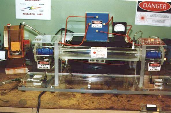
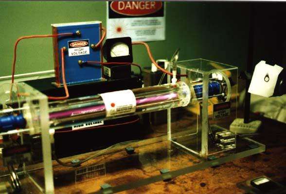
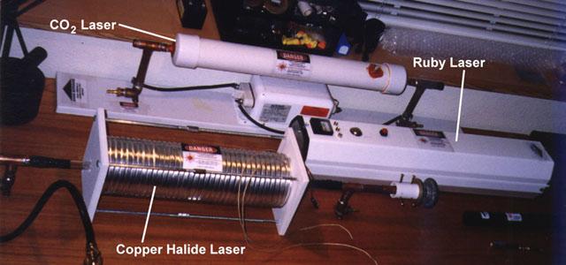
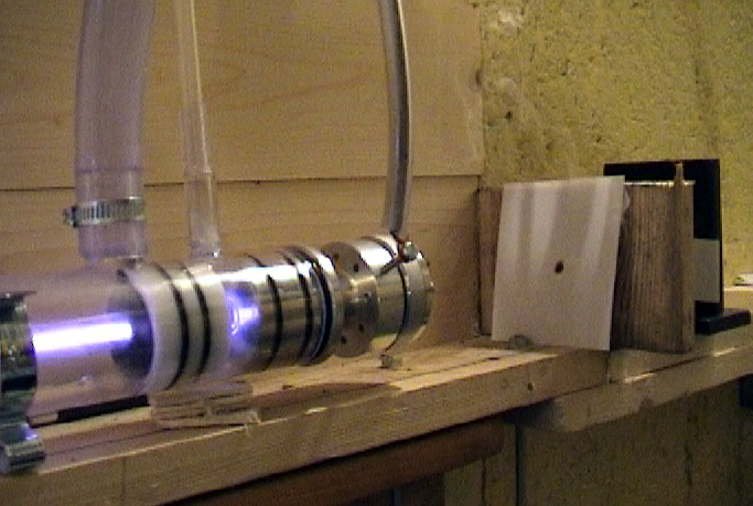