Currently, they are just suggestions. (If you can't wait, there are also some links to Web sites with educational laser projects below.) Eventually, additional details of the setup and required supplies will be added. Where the particular topic is already discussed elsewhere in Sam's Laser FAQ, a link to that section will be provided. However, in most cases, at least some of the details will be left as an exercise for the student. What fun or challenge would it be if we told you everything? After all, besides its educational value, hands-on experience should indeed be both fun and challenging! However, where more information is available in this document, links are provided.
A 1 to 5 mW internal mirror helium-neon laser will be suitable for most of the basic experiments (though a somewhat higher power one would be better for those like holography). It should be possible to procure such a laser for under $50, possibly under $25 depending on your resourcefulness and scrounging abilities.
Some experiments may require a polarized laser but for most, any type will do, even a better quality (one with an adjustable focusing lens) laser pointer - and those are practically given away in cereal boxes these days. :) Where access to the laser cavity is required, an external mirror HeNe or Ar/Kr ion laser will be needed. A one-Brewster HeNe laser setup can be put together quite inexpensively (probably under $100) using a surplus one-Brewster HeNe tube and power supply, the OC mirror from a deceased HeNe laser, and some scrap materials available in any well equipped junk box. Of course, if you have access to a nice lab laser, that would be fine as well but probably not nearly as much fun or as rewarding compared building one (at least partially) yourself. :)
Alternatives like bare laser diodes and appropriate drive circuitry may be more desirable for projects like laser communications where modulation is required. And, other color lasers (than the boring red HeNe or laser pointer) will be desirable for laser display.
See the chapter: Laser and Parts Sources. I also have a variety of suitable lasers and components available on Sam's Classified Page.
In addition, those experiments requiring access to the interior of the resonator of an external mirror laser may expose the user to potentially lethal voltages in the vicinity. If possible, any exposed high voltage terminals should be well insulated or blocked from accidental access. And, where all you have is an exposed HeNe laser tube and separate power supply, building all this into a safe enclosure is highly recommended.
Read the chapter: Laser Safety in its entirety and follow its guidelines - particularly in regards to the safety of others who may not be as aware as you in dealing with your equipment.
Basic principles:
Here is an optics site (not laser specific) oriented towards kids:
Also see the chapter: Laser Information Resources.
Now, what happens if multiple dielectric mirrors are placed in series? Under certain condition, more light will get through than might be expected. For example, using the same example as above, if T = .1 for both mirrors, the resulting output may actually be as high as for an equivalent mirror with T = .05 (rather than T = .01). Why? Under what conditions will this happen? How does the T factor of each mirror affect this behavior? What other factors are important?
(From: Skywise.)
I once made a two slit experiment using a piece of glass, two razor blades, some tape, and some water based acrylic paint.
First I painted the glass with the paint. I chose a dark green color which absorbed my HeNe light pretty well. To make a smooth single layer of paint I put two parallel strips of Scotch tape on the glass about 1/2 inch apart. Then I placed a drop of paint towards one end of the channel formed by the two pieces of tape. With a razor blade resting on the tape, I dragged the blade along the channel thus spreading a nice thin even coating of paint along the glass. With practice on how much pressure to apply I was able to get a very good strip of paint that wasn't too thick or thin.
While the paint dried I taped two razor blades stacked together. To get the razor edges closer together than the thickness of the blades I used a small piece of folded paper at the back edge of the blades so as to fulcrum the sharp edges of the blades closer together.
Once the paint was dried I quickly dragged the two points on the corner of the joined blades across the paint strip thus creating two parallel slits.
With practice on applying the paint, adjusting the gap of the blades, amount of pressure when scoring the paint, etc... I was able to successfully make two slits close enough that a raw beam from my 5 mW HeNe pointed at the two closely spaced slits caused diffraction in the far field.
It was quite fun and was very useful for demonstrating the wave nature of light.
More information with photos can be found in a link from: Skywise's Laser Picture Gallery.
See the sections starting with: Viewing Spectral Lines in Discharge, Other Colors in Output.
Locate a HeNe laser tube with an HR mirror that doesn't have any wedge and characterize its behavior. See the analysis in the section: Melles Griot Yellow Laser Head With Variable Output.
Here are some suggested experiments and questions to ponder using this rig:
More information can be found at the International School of Photonics Optogalvanic Page.
The optogalvanic effect can be observed even with a normal HeNe laser without external illuviation. As the tube warms up, the longitudinal modes shift through the gain curve and and the output power - and thus the intracavity power - changes depending on where the modes are. For long healthy tubes, the change is small. But for short tubes especially where the output power typically varies by 20 percent or more, it is easy to see as the sustaining voltage changing in synchrony with the power fluctuations.
Assuming a function generator and oscilloscope are available, it is possible to build an SFPI that demonstrates basic principles for next to nothing, or one that rivals the performance of commercial instruments costing many thousands of dollars for less than $100. See the sections starting with Sam's $1.00 Scanning Fabry-Perot Interferometer. Even this very simple SFPI using salvaged mirrors will easily resolve the longitudinal modes of a HeNe laser. I offer sets of mirrors suitable for a confocal HeNe laser mode display SFPI. See Sam's Classified Page under "HeNe Laser Kits".
All that is needed is a short HeNe laser tube to which a heater has been added, some optics and photodiodes to sample the amplitude of either one mode polarization or two mode (orthogonal) polarizations, and some basic electronic components to implement the control loop.
See the section Inexpensive Home-Built Frequency or Intensity Stabilized HeNe Laser for more information on what's involved.
I may be able to provide a set of parts including a well behaved HeNe laser tube, HeNe laser power supply, beamsplitter(s), photodiodes. Some mechanical skills will be required to mount everything. The electronic components can be obtained from places like Digikey or Jameco.
For looking at the longitudinal mode beating, a photodetector and oscilloscope with a response beyond c/2L for the HeNe laser will be required. This would be 500 MHz for a 12 inch long tube (mirror to mirror). So a longer tube would be desirable both due to its lower beat frequencies and more modes. For the second order difference frequencies, the photodetector still has to be fast but the scope only needs to respond to 100 kHz or so.
There are at least two arrangements primarily differing whether the magnetic field is oriented along the optical axis of the tube (axial) or perpendicular to it (transverse). Of course, no law prevents experimenting with the field at other orientations!
Here is a summary of the basic procedure for Zeeman splitting using an axial magnetic field. The following components are required:
Set up the components in a reasonably stable manner. The polarizer just needs to be in the beam - its orientation doesn't matter since it's simply converting circular to linear polarization.
Using a scope (preferably) or frequency counter, look for a beat frequency from the detector. The HP 5501 tube is very stable - its frequency will only vary by a few percent over several minutes. The frequency of the HP 5517 tube varies quite widely in a periodic manner as mode cycling takes place due to heating. The beat may disappear totally during part of the cycle. This behavior is very similar to that of the home-built version.
Adding some means of cavity length stabilization would be the next step.
Experiments can also be performed without the tube inside the ring magnets by trying various positions and orientations of external magnets. It may even be interesting to put the output through an audio amp and speaker as the beat frequency with a smaller magnetic field will cover the audio range.
Here is a summary of the basic procedure for Zeeman splitting using an transverse magnetic field. The following components are required:
Set up the components in a reasonably stable manner. It will be necessary to determine the natural polarization axes of the tube. Orient the magnets their field parallel to one of the axes and the polarizer at 45 degrees to one of the axis. Using a scope (preferably) or frequency counter, look for a beat frequency from the detector. Depending on magnetic field strength (i.e., how many magnets are used and how close they are to the tube), there will be a beat signal over part or all of the mode sweep cycle. Experiment with various configuration of the magnets.
To observe the polarized mode amplitudes, some additional optics for beam sampling will be required, along with photodiodes and possibly some simple electronics and a low speed data acquisition system to record the data.
This type of laser can also be frequency stabilized since the beat frequency varies with mode position. A Phase Locked Loop (PLL) is generally used but a simple Frequency-to-Voltage (F-V) converter and op-amp will work in a manner similar to that of the polarized mode stabilized lasers.
Many common materials like Nd:YAG have a small Verdet constant, though it is still sufficient to enable a strong magnet to produce enough of an FR effect to be used in forcing unidirectional operation of a ring laser. However, there are some special materials with very large Verdet constants. Terbium-doped glass has V = 65 deg/(T*cm) (T = Tesla = 10,000 gauss). And Terbium Gallium Garnet (Tb3Ga5O12 or TGG) has a Verdet constant about twice as large.
To put this in perspective, a 2 cm long rod of terbium-doped glass will rotate the polarization by 10 to 20 degrees if inserted inside a stack of two ferrite magnetron magnets. Even a "refrigerator" magnet of around 100 gauss will result in a detectable effect if the rod is between crossed polarizers or a polarizer is used with a linearly polarized laser. And 100 degrees or more is possible using a tabletop magnetic pulser. See the next section.
Pulser electronics:
The pulser dumps the energy in a charged capacitor bank using the flashlamp from a disposable camera as the switch. I'm using an unregulated linear HeNe laser power supply on a Variac as the capacitor charger for 5 uF at 2,000 to 2,500 V using a pair of 10 uF, 1,500 V capacitors in series with equalizing/bleeder resistors of 1.6M ohms on each. (Actually 4, 400K ohm, 2 W resistors in series.)
WARNING: The energy stored in this capacitor bank can be quite lethal. It's greater than that for a microwave oven capacitor.
The flashlamp has a self breakdown voltage of about 2,500 V so it alone can make a really big relaxation oscillator. But, the breakdown voltage is not nearly as consistent as with an NE2 neon lamp, so the rate of flashing using self-breakdown was highly erratic. So I used some of the remaining components from the flash unit to provide a manual trigger. The voltage for the trigger capacitor is taken across the bottom bleeder resistor. The single flashlamp is marginal at 2,500 V since it likes to fire on its own - two in series would probably be better. But this way, it lets me know not to try to push my luck at higher voltage. Most of my subsequent tests were done at just under 2,500 V so that it would not flash on its own. Charging requires about 15 seconds which results in a conservative average power for the solenoid, which would be the limiting component.
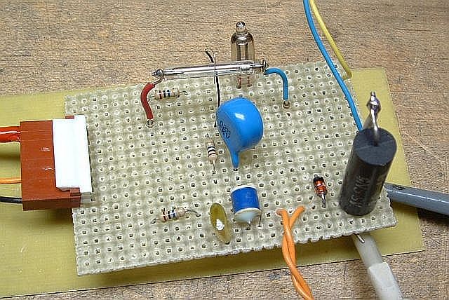
See Photo of Magnetic Pulser Flashlamp Switch and Trigger Circuit. The neon bulb will be lit when there is more than 60 V across the flashlamp so it serves as a danger indicator. The large blue capacitor isolates the trigger wire from the trigger transformer so that even if the flashlamp arced to the trigger wire, it wouldn't go any further. And note that the trigger wire isn't even near the flashlamp. When any closer, the flashlamp would self-fire at less than 2,000 V. The large black cylindrical object is the 0.2 ohm current sense resistor, with a scope probe and ground clip visible attached to it. The yellow and blue wires go to the pulser coil and the orange wires go to the remote trigger pushbutton.
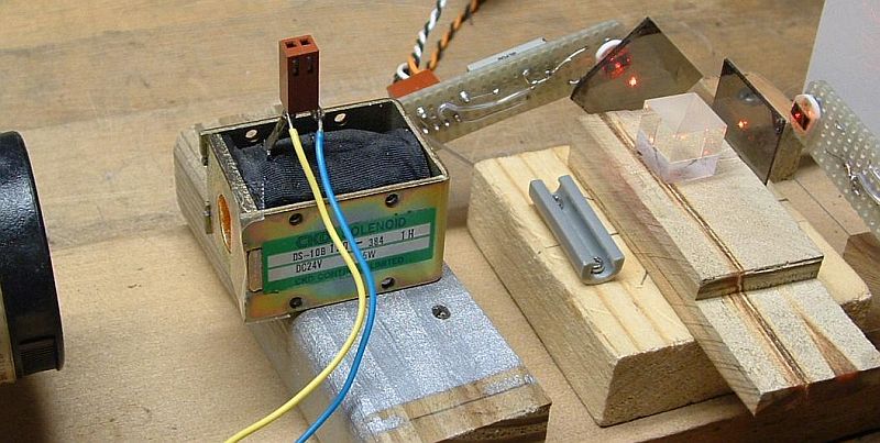
The pulser coil is from an actual magnetic solenoid used to actuate some sort of something or other. ;-) It was carefully selected because the bore size was correct for what had to go into it. :) With the rear pole piece drilled out and removed, it has a nice magnetic yoke to complete the magnetic circuit outside the bore of the solenoid. It's pure luck that this sort of thing survives being pummeled with pulses of nearly 2,500 V, as its normal operating voltage is 24 VDC. But so far so good.
Laser and optics:
I'm determining the magnetic field using a special type of magneto-optically active glass (M18, available at exorbitant cost from Kigre, though I'm sure if it's a listed product, mine is a sample on loan). This material exhibits a strong Faraday effect, rotating the polarization of a beam of light in proportion to the axial component of the magnetic field. The sensitivity of the Faraday Rotation (FR) in M18 is about 123.5 degrees per Tesla (10,000 gauss) for the 1.9 cm long rod. And, at nearly 2,500 V, I'm exceeding 1 T.
The very high class optical setup is shown in Optical Setup for M18 Faraday Rotation Experiments. Now these are true optical breadboards! :) It consists of a polarized 5 mW HeNe laser, the M18 rod (hidden inside the hole in the solenoid - note the piece of clear tape to prevent it from falling out accidentally if the solenoid is tipped!), a Melles Griot non-polarizing beamsplitter cube followed by a piece of Polaroid-type linear polarizer for each exit, and a reverse biased $2 photodiode with a 3.3K ohm load resistor.
While using a polarizing beamsplitter to obtain orthogonal vertically and horizontally polarized outputs might be expected and is often used in similar experiments, this is not optimal. Why? Because they don't provide much additional information compared to a single signal, being essentially complements of each-other. Having multiple signals may help reduce noise and eliminate offsets due to non-polarized light. However, they don't permit the determation of the direction of rotation if the input polarization is initially aligned with one of the polarizers (e.g., 0, 90, 180, or 270 degrees), or make it possible to disambiguate a change in rotation direction that may occur near one of these angles.
Therefore, in this setup, the polarizer for one of the photodiodes is oriented at 90 degrees but the other one is oriented at 45 degrees. Their outputs are called p and r, respectively. (The designations p and s are for polarizations at 90 degrees to each-other, thus the r instead of s. And, what I've called p may not be in universal agreement with everyone's definition. So, just think of them as two variables!) They provide quadrature signals in the same way as in a rotary encoder, so the output rotation will always be unambiguous. Since a full cycle of the polarization is 180 degrees rather than 360 degrees, the quadrature angle needs to be 45 degrees instead of 90 degrees but it's the same principle. (More on the angle doubling due to Malus' law below.)
The outputs of the photodiodes (PDs) go to the two channels of an analog scope, which unfortunately has no storage capability. This is one time I'd prefer a digital scope or data acquisition system! The trigger comes from a current sense resistor of 0.2 ohms, which was also used initially to determine the actual current in the coil. Since the scope has a "trigger view" function, the current (I) can be displayed as a third trace, since it is already used for triggering.
With the 5 uF energy storage capacitor bank, the pulse duration is about 2.5 ms and the system is just slightly underdamped. The peak current is 12 to 13 A into a coil with a resistance of 120 ohms. Based on the dimensions and resistance of the coil, it has approximately 2,700 turns of #32 AWG wire, producing more than 32,000 peak A-T. (This was found using the equations in the section: "Estimating the Number of Turns of Wire in a Coil" in the document: "Notes on the Troubleshooting and Repair of Small Household Appliances and Power Tools" of the Sci.Electronics.Repair FAQ.) However, the large number of turns results in a high inductance which is far from ideal. A smaller number of turns of thicker wire would be much better but scroungers can't always be too selective. For example, if there were 1/4 the number of turns of wire with 4 times the cross-sectional area, the resistance would be 1/16 and the current could be 16 times larger with the ampere-turns being 4 times as large so the magnetic field would be larger (subject to saturation effects of the iron of the yoke). This might be a bit much for the flashlamp from a disposable camera, but not for a larger one. Rewinding the solenoid might be possible but the yoke is not designed to be easily disassembled.
While the energy of the capacitor at 2,500 V is about 15 Joules, most of this is dissipated in the coil so the flashlamp isn't being stressed. I'd guess the dissipation there is under 1 Joule.
Plots of actual data:
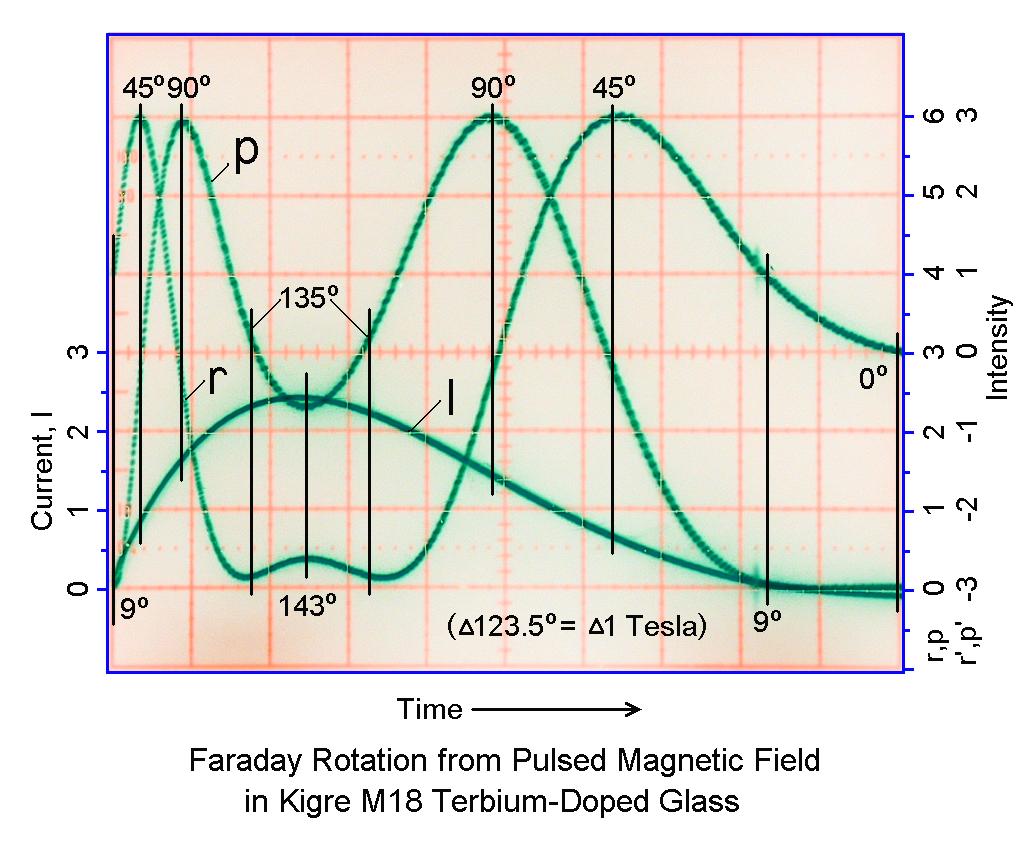
Faraday Rotation from Pulsed Magnetic Field in Kigre M18 Terbium-Doped Glass shows the results. Note that the initial angle is 9 degrees, not 0 degrees. The total change in rotation angle is about 134 degrees corresponding to a peak magnetic field of about 1.1 Tesla (11,000 gauss). This is a negative of a photo taken with a older cheap digital camera from an analog scope, thus the strange colors. :). (The camera has no sync input or output, and no manual focus. And, to get good contrast on the scope trace, the room had to be nearly dark - and autofocus wouldn't work. So, with the camera on a tripod, it came down to (1) turn the lights on to lock in focus and exposure by pressing shutter the button halfway, (2) turn the lights off while continuing to hold the shutter button halfway, (3) depress the shutter button fully to take the photo, (4) as soon as the fake click of the shutter opening is heard, press the trigger button on the pulser and hope this was done fast enough for the pulser to fire while the shutter is still open. It worked about 2/3rds of the time.)
Using the actual value of the current of 12 A measured with the 0.2 ohm sense resistor, the dimensions of the coil, and an estimate of the number of turns, the resulting magnetic field is 1.3 T, which is remarkably close to the measured value of 1.1 T considering all the assumptions and hand waving. :) There should be inaccuracies introduced because this coil has multiple layers and because there is an iron yoke completing part of the magnetic circuit.
The plot above shows the complete event except for the very tail of the current pulse. The three traces are the current, I (scale on the left) and r and p optical power (or intensity, scale on the right). A scale for signals r' and p' (to be described below) is also provided on the right. The units are arbitrary, based on the scope graticle. I believe the slight skew between r and p is a combination of the linear polarizers not being oriented at exactly 45 degrees and the beamsplitter cube transmission and reflection being slightly polarization-dependent even though it's supposed to be non-polarizing. The response of the M18 glass is very fast - probably in the 100s of GHz range if not higher - so that is not an issue here since these pulses are on the order of milliseconds.
Note that the electrical system is slightly underdamped so the current, and rotation angle, go a bit negative near the end. Faraday Rotation in Kigre M18 Glass - Complete Trace shows all the gory details. (Note that this is a different shot so the values are not quite identical.) When the current is descreasing and crosses zero going negative, the flashlamp is still conducting. But when the current attempts to cross zero going positive, the flashlamp apparently cuts off and thus the glitch before it flat-lines. Note that the magnitude of the negative current is quite small - less than 5 percent of the peak - but since r is changing rapidly at around that point, it looks a lot worse than it really is. The two pin connector attached to the solenoid terminals (visible in the photo) was intended for a snubber circuit to eliminate the undershoot, but it never was installed.
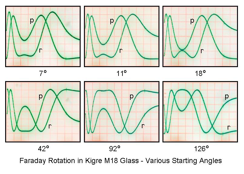
And, see Faraday Rotation in Kigre M18 Glass - Various Starting Angles for the appearance with the a bunch of randomly selected input polarizations, obtained by rotating the HeNe laser. :) (No effort was made to assure that the gain and offset of the r and p signals were exactly the same in each case, so they aren't.) Using a Half Wave Plate (HWP) in front of the laser to set the initial polarization angle, and for adjustment of the polarizers and detector electronics so the signals are precisely orthogonal and have equal gain and offset, would be better than rotating the entire laser since it will have no effect on beam alignment. However, the HWP would have to be closely matched to the laser wavelength to maintain pure linear polarization.
Calculating the rotation angle:
The rotation angle can be easily obtained using Malus' law and a bit of trigonometry. Remember that? :)
Malus' law relates the intensity of light passed by a polarizer to the angle between a linearly polarized input beam and the polarizer, or equivalently, to the angle between polarizers if using non-polarized light.
I = Io*cos(theta)2where Io is the intensity at 0 degrees and I is the actual intensity.
With a photodiode monitoring a fixed beam profile, intensity will be proportional to power. For the Faraday Rotation (FR) setup, there are a pair of polarizers offset by 45 degrees producing two signals, r and p:
   r = Io*[cos(theta-45)]2 and
   p = Io*[cos(theta)]2
where r and p are the actual photodetector signals with a minimum value of 0 and a maximum value of Io.
Note that this assumes both signals have the same minimum value (0) and maximum value (Io) as in the plot, above. Otherwise, appropriate adjustments should be made to eliminate any offset(s) and to make their scaling factor the same. I in fact did this by adjusting the vertical channel position and gain controls on the scope before taking the shots. This was done by rotating the laser to set the minimum and maximum on the display to be the same for both signals. Where they have already been captured, "adjustments" will need to be done on the data. This is left as an exercise for the student!
Continuing on using a basic trig identity:
   r = 0.5*Io*[1 + cos(2*(theta-45))] and
   p = 0.5*Io*[1 + cos(2*theta)]
This angle doubling is what results in 45 degrees being the required quadrature angle between r and p.
Simplifying:
   r = 0.5*Io*[1 + sin(2*theta)] and
   p = 0.5*Io*[1 + cos(2*theta)]
Then:
    r - 0.5*Io     sin(2*theta)
   ------------ = -------------- = tan(2*theta)
    p - 0.5*Io     cos(2*theta)
Solving for theta:
                       r-0.5*Io
   theta = 0.5*arctan(----------)
                       p-0.5*Io
Or defining the halfway point for r and p and using values relative to it, calling them r' and p', which may be intuitively easier:
                       r'
   theta = 0.5*arctan(----)
                       p'
Both equations are subject to the condition that the rotation function must be continuous. A value of +/-(n*90) or +/-(n*180) degrees may need to be added to theta to achieve this since the arctan function can fall into the wrong quadrant.
I used MS Excel to confirm expected behavior for the data in the plots, above. In addition, the angles were estimated using the current trace relative to maximum current (based on values in the plot normalized to the peak magnetic field as determined from r' and p'). All the annotated angles are included along with a few intermediate easy to record ones:
   PD Signals             Angle   Angle from  Sensed   Angle from
    r'     p'   2*theta   Adjust   r' and p'  Current   Current
 ------------------------------------------------------------------
   1.00  -2.95  -18.7°      +0°       9.4°     0.15       11.6°
   2.00  -2.00  -45.0°      +0°      22.5°     0.45       29.1°
   3.00   0.00   90.0°     +90°      45.0°     0.80       49.4°
   2.00   2.00   45.0°     +90°      67.5°     1.25       75.6°
   0.00   3.00    0.0°     +90°      90.0°     1.65       98.9°
  -2.00   2.00  -45.0°     +90°     112.5°     2.00      119.3°
  -2.90   0.15  -88.0°     +90°     133.5°     2.30      136.7°
  -2.60  -0.70   74.9°    +180°     142.5°     2.40      142.5°
  -2.90   0.15  -88.0°     +90°     133.5°     2.20      130.9°
  -2.00   2.00  -45.0°     +90°     112.5°     1.85      110.5°
   0.00   3.00    0.0°     +90°      90.0°     1.40       84.4°
   2.00   2.00   45.0°     +90°      67.5°     1.05       64.0°
   3.00   0.00   90.0°     +90°      45.0°     0.65       40.7°
   2.00  -2.00  -45.0°      +0°      22.5°     0.30       20.4°
   1.00  -2.95  -18.7°      +0°       9.4°     0.05        5.8°
   0.00  -3.00    0.0°      +0°       0.0°    -0.05        0.0°
   1.00  -2.95  -18.7°      +0°       9.4°     0.10        8.7°
The values for r', p', and current (I) are from the plots and not volts or amps! And they were only slightly fudged. :) Due to the small skew in the r and p polarizers, I had to estimate some values where one of the signals was changing rapidly and didn't line up with the other as expected. In principle, I could go back and reshoot the data but that isn't going to happen! I was also trying to reconcile my inability to match up the magnetic field from the r and p signals compared to the magnetic field predicted by based on current. Then I realized that there is real hysteresis in the response of the solenoid's magnetic field with respect to the current. The magnetic field lags behind the current. So, the actual magnetic field (from r and p) is smaller than what would be predicted based on ampere-turns when the current is increasing and larger when the current is decreasing. Interesting. It's also possible that some or all of the hysteresis is in the response of the M18 glass to the magnetic field but based on what is found in the literature, this doesn't seem very likely.
Why the Faraday rotation experiments were done:
The reason I got involved is that a grad student at Cornell is using the stuff to measure high magnetic fields in plasma physics experiments and I decided I wanted to play as well. The peak magnetic fields involved in the research are only about 50 percent greater than what I have achieved, but the pulse duration is shorter by nearly 4 orders of magnitude. This requires more expensive detectors, high speed data acquisition, and super shielding in the vicinity of million amp current pulses, but is fundamentally the same problem. I will describe the actual details in the future. :-) But for now, see Magnetic Field Measurements in Wire Array Z-Pinches (Poster) and Magnetic Field Measurements in Wire Array Z-Pinches and X-Pinches (Paper) if you are curious. But more recent results are far more convincing.
                                                      o--- NC (Light)
                                            COM ---o/
                                                      o--- NO (No light)
       +6 V o-------+---------+---------------+----+
   (4 AA Cells)     |         |               |    |
                    |         \              _|_    )|| K1
                    /         / R3    1N4148 /_\    )|| 6V coil
                    \ R1      \ 1.5K          |     )|| 500 ohms
                    / 3.3K    /               |    |
                    \         |               +----+
                    |         |                    |
                  __|__       |      5.6K      B |/ C
     LIGHT ---->  _/_\_ PD1   +------/\/\--------|    Q2 2N3904
          Sensor    |         |                  |\ E
        Photodiode  |     B |/ C                   |
         PDB-V107   +-------|    Q1 2N3904         |
                    |       |\ E                   |
                    \         |                    |
                 +->/ R2      |                    |
                 |  \ 100K    |                    |
                 |  / Sens.   |                    |
                 |  |         |                    |
    Return o-----+--+---------+--------------------+
Basic experiements can be performed with just a laser pointer, solar cell, and audio amp. However, keep in mind that to really get any decent performance is not a trivial undertaking. Sound is likely to be distorted and noisy with contributions from both inside and outside. And just getting enough optical return off a window unless at precisely normal incidence will be a challenge in itself. Here is one link that appears to have rather detailed information: Laser Microphone.
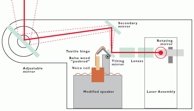
Ever since I first ripped apart a laser printer I've known that those spinning mirrors and weird optics would be perfect for a laser oscilloscope, but I didn't have any lasers powerful enough and didn't really know where to begin, so the idea just kept rattling around in my head. Until now. A while ago I came upon a cheapo video DVD-burner with a fried PSU. That was the laser I'd been waiting for. And largely thanks to this amazing site, I found out how to use it.
The thing is built around a square rotating mirror sweeping the laser beam, a few flat lenses pulling the sweep together to about 30 degrees, and a speaker voice-coil tilting a long narrow mirror around a hinge. Bror Westblad's Mark-I Laser Oscilloscope Optical Path. Through the "Amplified Ear" AGC amp from RED Free Circuit Designs, a microphone picks up any sound in the room and displays it on a nervous red line on the wall. The effect is quite eerie, but on a well lit gallery wall it doesn't have quite the visual punch I was hoping for. It appears that even a painfully bright laser spot becomes rather feeble when stretched out to a two meter long line.
Here's all I know about the laser: The DVD-burner was dead, so I just ripped out the optical module, and, as it seemed people do that sort of thing, I hooked up the laser straight to two not so peppy Duracell rabbits and, hey presto, light! Then I looked into power supplies, and ended up building SG-LD1. That worked perfectly when I tested it with dummy LEDs and a photodiode. But not with the laser! The LD is an "open can" thing, which let me inspect it properly with a 24x magnifier and, what do you know, there is nothing connected to the PD pin! (The pin was soldered to ground/case in the unit, but I wrongfully assumed that it just wasn't in use. Well, it wasn't even there!)
So, I ended up building that super simple LM317 PSU. And now it works. But, I've no idea how much current I can feed the laser. The thing is, when I turn the power up, the output increases smoothly and I don't really see any distinct threshold. At 60 mA the output is about as bright as from a regular 1mW laser pointer. When I initially tested the laser with the batteries it drew 84 mA, so I guessed that to be some sort of max limit. So, in the final assembly, I adjusted the current to 81 mA.
Bror Westblad's Mark-I Laser Oscilloscope with Cover Removed is an annotated photo of the completed unit.
(From: Sam.)
You were quite lucky (assuming that it wasn't damaged by the initial test with the two Alkaline cells! The 84 mA just happened to be all the pooped out battery could deliver.
There is no real way to know what the upper limit is without either knoing the LD part number, or destroying a few. But many DVD burner LDs go up to 100 mW or more.
One of my students built a real time (60 iterations per second on a 512 x 512 grid) implementation using conventional video technology about 20 years ago. When displayed in this manner, the appearance can be truly mesmerizing.
This would be a natural for a laser display. The dimensions would not be restricted to common video formats but could be anything reasonable. While custom digital hardware including a full frame store had to be built 20 years ago to produce a real-time update rate, nowadays, a modern PC may be fast enough to result in an acceptable presentation.
A typical front surface aluminized mirror reflects about 90 to 95 percent of the light so there can be quite a few bounces before the beam loses so much intensity as to be undetectable. However, the quality of the mirror is also important so as not to distort or scatter the beam. Sources for these mirrors include barcode scanners and laserprinters. Back surface mirrors are considerably worse than front surface mirrors. Dielectric mirrors coated for the specific laser wavelength are by far the best, some reflecting 99.999 percent of the light.