For current production lasers, the manufacturers' Web sites often provide basic specifications. For older lasers, it's often difficult to obtain detailed specs so estimates based on physical size, and then testing may be the only option.
Unless otherwise noted (below), these were obtained from brochures, spec sheets, or user manuals for each laser. Contributions and corrections welcome.
All values are in parts per billion (ppb).
                         <---- Frequency Stability Time Scale ---->
   Model                  Sec   Min    Hour    Day    Year    Life
--------------------------------------------------------------------------
 Aerotech S100 (2)              +/-1   +/-4   +/-4 (8 hours)
 Coherent 200                   +/-2 (5 min)         +/-10 (long term)
 Excel 1001A/B/F              20 (unspecified time)
 Excel 1100B                  20 (unspecified time)
 HP 5500A/C, 5501A                            +/-2           +/-20
 HP 5501B                                     +/-2           +/-20
 HP/Agilent 5517 (all)                        +/-2           +/-20
 Jenaer ZL 600                 5 (unspecified time)
 Laseangle RB-1 (3)      0.01   0.1
 Lab for Science 200     0.03   0.05   0.2     0.5
 Lab for Science 210     0.03   0.05   0.2     0.5
 Lab for Science 220     0.01   0.02   0.05    0.2
 Lab for Science 260     0.02   0.02   0.1     0.4
 Limtek LS 10.3               20 (unspecified time)
 Mark-Tech 7900                               +/-2 (constant temperature)
 Mark-Tech 7910 (6)
 Melles Griot 05-STP-901 (4)    +/-1   +/-4   +/-4 (8 hours)
 Melles Griot 05-STP-91X (2)    +/-2   +/-4   +/-6 (8 hours)
 Micro-G  ML-1         0.08-0.15 (unspecified time, constant temperature)
 NEOARK NEO-262                1 (unspecified time)
 Newport NL-1
 Nikon
 NPL Hexagon                           -.01                   +/-2
 NPL I2 543 nm                                               +/-0.25
 NPL I2 633 nm                                               +/-0.2
 Optodyne L-109
 Renishaw ML10
 Renishaw XL80
 REO SHL                        +/-2   +/-4   +/-6
 SIOS SL 02                     +/-2   +/-10  +/-20
 SIOS SL 03                     +/-1   +/-2   +/-10
 Spectra-Physics 117 (5)
 Spectra-Physics 117A (4)       +/-1   +/-4   +/-4 (8 hours)
 Spectra-Physics 117C (5)
 Spectra-Physics 119 (7)                      +/-2
 Teletrac/Axsys 150-IV
 Zygo 7701/7702                        +/-2   +/-10  +/-100
 Zygo 7705                             +/-10  +/-20  +/-200
 Zygo 7712/7714                        +/-0.5 +/-1
 Zygo 7722/7724                        +/-0.5                +/-10
Notes:
All Melles Griot HeNe laser tubes are hard-sealed with essentially unlimited shelf life - 12 years is quoted but for all practical purposes, it is infinite. Most standard tubes have a planar HR mirror with a concave OC mirror with its curvature selected for maximum stability. This long radius hemispherical cavity configuration puts the beam waist at the HR with a slightly diverging beam from the OC. But a compensating curvature on the outer surface of the OC mirror of most laser tubes that are sold as or in standard products results in a positive lens and the beam that exits the laser is quite well collimated. (Specific applications like barcode scanning may call for a divergence other than the minimum possible to avoid the need for an additional external lens.)
And in the "I always wondered about that" department, the correct way to pronouce Melles Griot is
MEL-liss (emphasis on the first syllable).
GREE-o (emphasis on the first syllable).
This was confirmed both by someone who knew Jan Melles and Richard Griot personally, and from a VP at Melles Griot. But apparently, some of their employees don't even get it right. :)
The following data came from a variety of sources including an old Melles Griot brochure, the 1999 catalog, and the Melles Griot Web site. Go to "Product Info", "Lasers", "HeNe" or more directly to Melles Griot Lasers, "Helium-Neon (HeNe)". Then click on any location.
This is not a complete list but probably includes most of those you're likely to come across.
Red (632.8 nm):
  Minimum  e/2               c/2L      Supply    Nominal               (1)
  Output   Beam    Diver-    Mode     Opr/Strt    Tube    Tube Size   Model
  Power    Diam    gence    Spacing   (Rb=75K)   Current  Diam/Lgth  05-LHR/P-
 ------------------------------------------------------------------------------
   .4 mW  .34 mm  2.40 mR  1360 MHz  1.22/5  kV  3.2 mA   23/118 mm    007
   .5 mW  .46 mm  1.70 mR  1272 MHz  1.18/5  kV  4.5 mA   25/127 mm    640
   .5 mW  .47 mm  1.70 mR  1200 MHz  1.29/5  kV  3.3 mA   19/135 mm    002(2)
   .5 mW  .46 mm  1.77 mR  1063 MHz  1.32/5  kV  4.0 mA   25/150 mm    213
   .5 mW  .49 mm  1.70 mR  1040 MHz  1.25/5  kV  4.5 mA   29/152 mm    700
   .5 mW  .50 mm  1.61 mR  1039 MHz  1.29/5  kV  4.5 mA   37/152 mm    604
   .6 mW  .47 mm  1.70 mR  1078 MHz  1.43/5  kV  4.0 mA   25/146 mm    004
   .6 mW  .85 mm  0.95 mR   787 MHz  1.29/5  kV  4.5 mA   37/200 mm    410
   .8 mW  .47 mm  1.70 mR  1078 MHz  1.33/5  kV  3.0 mA   25/149 mm    006
   .8 mW  .46 mm  1.77 mR  1063 MHz  1.32/5  kV  4.0 mA   25/150 mm    211
   .9 mW  .47 mm  1.70 mR  1078 MHz  1.38/5  kV  3.3 mA   25/147 mm    049
   .9 mW  .48 mm  1.70 mR  1100 MHz  1.20/5  kV  4.0 mA   25/146 mm    704
   .9 mW  .48 mm  8.00 mR  1078 MHz  1.31/5  kV  3.5 mA   25/145 mm    041
   .9 mW  .65 mm  1.24 mR   862 MHz  1.05/5  kV  4.0 mA   28/183 mm    041
  1.0 mW  .53 mm  1.50 mR   883 MHz  1.47/8  kV  4.5 mA   29/178 mm    900
  1.0 mW  .59 mm  1.35 mR   687 MHz  1.79/8  kV  6.5 mA   37/226 mm    110
  1.0 mW  .66 mm  1.25 mR   683 MHz  1.10/8  kV  3.5 mA   28/227 mm    101
  1.5 mW  .53 mm  1.50 mR   889 MHz  1.71/8  kV  4.5 mA   25/178 mm    008
  1.5 mW  .58 mm  1.39 mR   793 MHz  1.66/8  kV  5.0 mA   37/228 mm    130

  2.0 mW  .49 mm  1.65 mR   638 MHz  1.45/10 kV  3.7 mA   29/243 mm    038
  2.0 mW  .55 mm  1.47 mR   822 MHz  1.94/10 kV  4.5 mA   25/191 mm    009
  2.0 mW  .59 mm  1.35 mR   687 MHz  1.77/10 kV  6.5 mA   37/226 mm    219
  2.0 mW  .59 mm  1.35 mR   687 MHz  1.79/10 kV  6.5 mA   37/228 mm    120
  2.0 mW  .63 mm  1.40 mR   641 MHz  1.82/10 kV  4.5 mA   29/241 mm    088
  2.0 mW  .72 mm  1.10 mR   612 MHz  1.85/10 kV  6.5 mA   29/255 mm    080
  2.0 mW  .76 mm  1.06 mR   638 MHz  1.57/10 kV  4.5 mA   29/243 mm    097
  2.0 mW  .76 mm  1.06 mR   636 MHz  1.71/10 kV  5.0 mA   30/250 mm    073
  2.0 mW  .79 mm  1.00 mR   574 MHz  1.81/10 kV  6.5 mA   37/270 mm    320
  2.5 mW  .52 mm  1.53 mR   822 MHz  1.77/10 kV  4.5 mA   25/198 mm    690
  2.7 mW  .58 mm  1.41 mR   694 MHz  1.81/10 kV  4.5 mA   28/226 mm    082
  4.0 mW  .80 mm  1.00 mR   438 MHz  2.29/10 kV  6.5 mA   37/353 mm    140
  5.0 mW  .80 mm  1.00 mR   438 MHz  2.29/10 kV  6.5 mA   37/353 mm    150
  7.0 mW 1.02 mm   .79 mR   373 MHz  2.65/10 kV  6.5 mA   37/410 mm    170

  10 mW   .65 mm  1.24 mR   341 MHz  2.64/10 kV  6.5 mA   37/440 mm    991
  12 mW  1.20 mm  3.40 mR    NA-MM   2.09/10 kV  6.5 mA   37/350 mm    185(3)
  16 mW  1.47 mm  1.40 mR    NA-MM   2.48/10 kV  7.0 mA   37/464 mm    981(3)
  17 mW   .96 mm   .83 mR   267 MHz  3.70/12 kV  7.0 mA   37/600 mm    825
  17 mW   .96 mm   .83 mR   267 MHz  3.70/12 kV  7.0 mA   37/600 mm    925
  25 mW  1.23 mm   .66 mR   165 MHz  5.10/15 kV  8.0 mA   42/930 mm    827
  25 mW  1.42 mm  2.40 mR    NA-MM   3.20/10 kV  7.0 mA   42/590 mm    831
  35 mW  1.23 mm   .66 mR   165 MHz  5.10/15 kV  8.0 mA   42/930 mm    927
  35 mW  1.23 mm   .66 mR   165 MHz  5.10/15 kV  8.0 mA   42/930 mm    928(4)
Notes:
LHR models are random polarized; LHP models are linearly polarized. Not all model numbers have both versions. Barcode scanning tubes are nearly all only available random polarized.
For lower power lasers, models ending in an even number are often (but not always) a bare tube, with the corresponding head being the same number incremented by (or ORed with) 1. For high power lasers, the laser head number is listed.
The operating voltage across the tube itself can be found by subtracting the voltage drop across the ballast resistor (I*Rb), from the value listed in the table. Actual starting voltages are typically 3 to 5 times the tube operating voltage (though the specifications may be higher). Note that I've assumed a 75K ballast resistance for all tubes. The actual manufacturer recomendation may differ slightly but 75K should be acceptable for most.
Both random (LHR) and linearly polarized (LHP) models are available for most of the lasers listed above. The only other difference in specifications for red HeNe lasers between these is their price - about 10 to 15 percent higher for a complete polarized laser. So you can imagine the difference in the tube cost alone since everything else is identical. (The output power of "other-color" linearly polarized HeNe lasers compared to similar size random polarized models, particularly for yellow and green which have very low gain, tends to be much less since the losses through the internal Brewster plate become more significant.)
And speaking of prices, if you have to ask, you can't afford a new HeNe laser! But since you asked, prices (Summer 2002) from Melles Griot vary from around $300 for a 0.5 mW laser head to over $4,000 for one rated at 35 mW (power supply sold separately)! Prices in Summer 2005 haven't changed that much but only complete systems can be ordered on-line. Prices: $587.83 (0.5 mW) to $4,532.88 (35 mW). Fortunately, surplus prices tend to be much more reasonable - typically between 5 and 20 percent of these depending on actual age and condition as well as many other factors including your luck in finding a good deal. :)
Green (543.5 nm), random polarization:
  Minimum  e/2               c/2L      Supply    Nominal
  Output   Beam    Diver-    Mode     Opr/Strt    Tube    Tube Size   Model
  Power    Diam    gence    Spacing   (Rb=75K)   Current  Diam/Lgth  05-LGR-
 -----------------------------------------------------------------------------
  .08 mW  .88 mm  2.35 mR    NA-MM    .88/8  kV  3.7 mA   25/149 mm    004
   .2 mW  .63 mm  1.26 mR   732 MHz  1.56/8  kV  4.5 mA   29/215 mm    025
   .2 mW  .75 mm   .92 mR   373 MHz  2.62/10 kV  6.5 mA   37/410 mm    171
   .3 mW  .81 mm   .99 mR   574 MHz  2.20/10 kV  6.5 mA   37/269 mm    321
   .5 mW  .80 mm  1.01 mR   438 MHz  2.39/10 kV  6.5 mA   37/351 mm    141
   .5 mW  .80 mm  1.01 mR   438 MHz  2.39/10 kV  6.5 mA   37/351 mm    151
   .5 mW 1.35 mm  1.10 mR    NA-MM   1.94/10 kV  6.5 mA   37/351 mm    252
   .8 mW  .89 mm   .92 mR   373 MHz  2.62/10 kV  6.5 mA   37/410 mm    173
  1.0 mW  1.3 mm  1.00 mR    NA-MM   1.87/10 kV  6.5 mA   37/351 mm    161
  1.0 mW  .80 mm   .86 mR   328 MHz  2.75/10 kV  6.5 mA   37/475 mm    293
  1.5 mW  .86 mm   .81 mR   328 MHz  2.75/10 kV  6.5 mA   37/475 mm    193
  2.0 mW  .86 mm   .81 mR   328 MHz  2.75/10 kV  6.5 mA   37/475 mm    393
Green (543.5 nm), linear polarization:
  Minimum  e/2               c/2L      Supply    Nominal
  Output   Beam    Diver-    Mode     Opr/Strt    Tube    Tube Size   Model
  Power    Diam    gence    Spacing   (Rb=75K)   Current  Diam/Lgth  05-LGP-
 -----------------------------------------------------------------------------
   .2 mW  .75 mm   .92 mR   373 MHz  2.62/10 kV  6.5 mA   37/410 mm    171
   .2 mW  .77 mm   .90 mR   438 MHz  2.39/10 kV  6.5 mA   37/351 mm    141
   .3 mW  .77 mm   .90 mR   438 MHz  2.39/10 kV  6.5 mA   37/351 mm    151
   .3 mW  .86 mm   .89 mR   373 MHz  2.62/10 kV  6.5 mA   37/410 mm    173
  1.0 mW  .86 mm   .81 mR   328 MHz  2.75/10 kV  6.5 mA   37/475 mm    293
Yellow (594.1 nm), random polarization:
  Minimum  e/2               c/2L      Supply    Nominal
  Output   Beam    Diver-    Mode     Opr/Strt    Tube    Tube Size   Model
  Power    Diam    gence    Spacing   (Rb=75K)   Current  Diam/Lgth  05-LYR-
 -----------------------------------------------------------------------------
  .?? mW  ??? mm  ?.?? mR    NA-MM    .??/5  kV  3.? mA   25/149 mm    006
  .35 mW  .63 mm  1.26 mR   732 MHz  1.62/8  kV  4.5 mA   29/215 mm    025
  .35 mW  .69 mm  1.09 mR   574 MHz  1.95/10 kV  6.5 mA   37/269 mm    320
  .75 mW  .80 mm  1.01 mR   438 MHz  2.43/10 kV  6.5 mA   37/351 mm    151
  1.0 mW  .75 mm   .92 mR   373 MHz  2.59/10 kV  6.5 mA   37/410 mm    171
  2.0 mW  .75 mm   .92 mR   373 MHz  2.59/10 kV  6.5 mA   37/410 mm    173
  2.0 mW  1.17 mm 1.00 mR    NA-MM   2.09/10 kV  6.5 mA   37/351 mm    161
Yellow (594.1 nm), linear polarization:
  Minimum  e/2               c/2L      Supply    Nominal
  Output   Beam    Diver-    Mode     Opr/Strt    Tube    Tube Size   Model
  Power    Diam    gence    Spacing   (Rb=75K)   Current  Diam/Lgth  05-LYP-
 -----------------------------------------------------------------------------
  1.0 mW  .75 mm   .92 mR   373 MHz  2.59/10 kV  6.5 mA   37/410 mm    173
Orange (611.9 nm), random polarization:
  Minimum  e/2               c/2L      Supply    Nominal
  Output   Beam    Diver-    Mode     Opr/Strt    Tube    Tube Size   Model
  Power    Diam    gence    Spacing   (Rb=75K)   Current  Diam/Lgth  05-LOR-
 -----------------------------------------------------------------------------
   .5 mW  .63 mm  1.26 mR   732 MHz  1.66/8  kV  4.5 mA   29/215 mm    025
  2.0 mW  .80 mm  1.01 mR   438 MHz  2.49/10 kV  6.5 mA   37/351 mm    151
  4.0 mW  1.17 mm 1.00 mR    NA-MM   2.07/10 kV  6.5 mA   37/351 mm    161
Infra-Red (1,523 nm), random polarization:
  Minimum  e/2               c/2L      Supply    Nominal
  Output   Beam    Diver-    Mode     Opr/Strt    Tube    Tube Size   Model
  Power    Diam    gence    Spacing   (Rb=75K)   Current  Diam/Lgth  05-LIR-
 -----------------------------------------------------------------------------
  0.5 mW 1.26 mm  1.59 mR   438 MHz  2.49/10 kV  6.5 mA   37/351 mm    151
  1.0 mW 1.33 mm  1.48 mR   373 MHz  2.97/10 kV  6.0 mA   37/410 mm    171
Infra-Red (1,523 nm), linear polarization:
  Minimum  e/2               c/2L      Supply    Nominal
  Output   Beam    Diver-    Mode     Opr/Strt    Tube    Tube Size   Model
  Power    Diam    gence    Spacing   (Rb=75K)   Current  Diam/Lgth  05-LIP-
 -----------------------------------------------------------------------------
  0.4 mW 1.26 mm  1.59 mR   438 MHz  2.49/10 kV  6.5 mA   37/351 mm    151
  0.8 mW 1.33 mm  1.48 mR   373 MHz  2.97/10 kV  6.0 mA   37/410 mm    171
Infra-Red (3,391 nm), random polarization:
  Minimum  e/2               c/2L      Supply    Nominal
  Output   Beam    Diver-    Mode     Opr/Strt    Tube    Tube Size   Model
  Power    Diam    gence    Spacing   (Rb=75K)   Current  Diam/Lgth  05-LFR-
 -----------------------------------------------------------------------------
  1.0 mW  .83 mm  1.60 mR   438 MHz  2.50/10 kV  6.0 mA   37/351 mm    151
Infra-Red (3,391 nm), linear polarization:
  Minimum  e/2               c/2L      Supply    Nominal
  Output   Beam    Diver-    Mode     Opr/Strt    Tube    Tube Size   Model
  Power    Diam    gence    Spacing   (Rb=75K)   Current  Diam/Lgth  05-LFP-
 -----------------------------------------------------------------------------
  1.0 mW  .83 mm  1.60 mR   438 MHz  2.50/10 kV  6.0 mA   37/351 mm    151
Note: Some of the listed values for divergence in particular appear to be questionable. For example, for the same beam diameter, diffraction limited divergence should be proportional to wavelength. The discrepency for the 3,391 nm IR tube is particularly striking. Either the divergence or beam diameter are almost certainly incorrect. It probably doesn't matter much though because the 3,391 nm model is no longer manufactured. I also suspect the output power rating for the 05-LGR-171 may be a bit higher than listed in the source for this information.
Brewster angle window HeNe tubes:
      Minimum   Supply    Supply   Nominal                      Number
      Output    Voltage   Voltage   Tube    Tube Size   Model     of
      Power    Tube Only  Rb=68K   Current  Diam/Lgth  05-LHB-  Windows
     -------------------------------------------------------------------
      1.0 mW    1,430 V   1,870 V   6.5 mA  37/222 mm    270       1
      1.0 mW    1,460 V   1,900 V   6.5 mA  37/253 mm    290       2
      3.5 mW    1,080 V   1,520 V   6.5 mA  37/265 mm    370       1
      4.0 mW    1,030 V   1,470 V   6.5 mA  37/265 mm    570       1
      ??? mW    1,??? V   1,??? V   6.5 mA  37/265 mm    580       1
      6.0 mW    1,430 V   1,870 V   6.5 mA  37/351 mm    670       1
The most common application for one-Brewster HeNe tubes was probably for particle counting since by using an external high quality HR mirror, the intracavity flux can be several watts which makes a speck of anything stand out! (Some large one-Brewster HeNe tubes can do as much as 100 W intracavity, not these!). Passing the air/gas/whatever flow through the cavity of a one-Brewster HeNe laser is similar to passing it through the output beam of a high power laser - at a fraction of the cost (and it's much safer as well since if anything macroscopic in size (like an eyeball or piece of paper) were to block the intracavity beam, lasing simply stops with no damage to vision and no risk of fire!
The LHB models all have HR mirrors that are probably optimal for 632.8 nm (red) though newer versions, at least, may be quite broadband and better than 99.9 percent from 590 to 680 nm so operation at some of the non-632.8 nm wavelengths may be possible. However, older versions may not have such nice HRs.
Other variations on these tubes are also produced (though they may be special order). I was given an 05-LGB-580 which has an HR optimized for 543.5 nm (green). With an external green HR, the behavior is very similar to the red version but with loads of circulating green photons instead of red ones. :) I was told that this tube may have been made for the sole purpose of confirming the quality of the mirrors to be used in normal internal mirror HeNe laser tubes. So, I doubt you could buy 1. Maybe 1,000, but not just 1! Applications for such a tube would be very limited due to the low gain as it stops lasing entirely in a few minutes after cleaning the optics just due to dust settling on the B-window.
The 05-LHB-370, 05-LHB-570, 05-LHB-670, and 05-LHB-580 have wide bores and generally operate with multiple transverse modes to achieve maximum intracavity power in particle counting applications. The 05-LHB-270 and 05-LHB-290 have narrow bores like most conventional HeNe tubes. (The 05-LHB-270 appears physically similar to an 05-LHR-120 except for the Brewster window at one end.) The model 05-LHB-570 is the one-Brewster HeNe tube used in the CLIMET 9048 one-Brewster laser head described in the section: A One-Brewster HeNe Laser Tube. You can't tell from the model numbers but both Melles Griot and Hughes style designs may be used. For example, the 05-LHB-570 looks like a normal Melles Griot tube but with a Brewster angle window frit sealed to the metal end-cap instead of an OC mirror. The 05-LHB-580 looks like a Hughes style tube, but with an optically contacted Brewster window instead of an OC mirror (though some Hughes style polarized HeNe tubes are just one-Brewster tubes with an OC mirror attached to a glass tube that slips over the Brewster stem and is itself glued in place). Thus, the 05-LHB-580 is actually a much higher quality (and more expensive) tube than the 05-LHB-570 but you can't tell this from the catalog listing! Here are diagrams of each type:
One possible explanation of why the Hughes style design is used for the high quality tubes with optically contacted Brewster windows is that since Hughes already produced HeNe tubes with a glass Brewster stem (as noted above), when Melles Griot took over the Hughes HeNe laser product line, making the modifications for the graded seal to accommodate the fused silica Brewster stem (needed to match the expansion coefficient of the fused silica window) was probably easier than starting with a metal end-cap.
Zero degree AR coated window HeNe tubes:
      Minimum   Supply    Supply   Nominal                      Number
      Output    Voltage   Voltage   Tube    Tube Size   Model     of
      Power    Tube Only  Rb=68K   Current  Diam/Lgth  05-WHR-  Windows
     -------------------------------------------------------------------
      4.0 mW    1,030 V   1,470 V   6.5 mA  37/269 mm    570       1
      6.0 mW    1,670 V   2,110 V   6.5 mA  37/351 mm    252       2
      8.0 mW    1,670 V   2,110 V   6.5 mA  37/351 mm    183       1
Rather than mirrors, one or both ends of these HeNe tubes have optical flats with very high quality AR coatings to permit the use of external mirrors. One advantage of this arrangement is that external optics can be used to control polarization (the output beam of Brewster tubes is always linearly polarized and can't be changed).
The 05-WHR-252 and 05-WHR-183 appear to be identical except for the number of windows - and the loss of 2 mW with the two window version!
Here are the optical and stabilization specifications for the 05-STP-901 (from Melles Griot):
 Optical Specifications
----------------------------------------------
 Output Wavelength:               633 nm
 Output Power:                      1 mW
 M2:                               <1.1
 Beam Diameter (1/e2):            0.5 mm
 Far-Field Divergence (1/e2):    1.60 mrad
 Polarization:                 Linear, >1000
 Mode:                            TEM00

 Stabilization Characteristics - Frequency Stabilized Mode
-------------------------------------------------------------
 Frequency Stability (1 min/1 hr/8 hr):   +/-0.5/2.0/2.0 MHz
 Power Stability (1 min/1 hr/8 hr):       1.0% rms
 Frequency Offset:                        +/-150 MHz
 Temperature Dependence:                  0.5 MHz/°C

 Stabilization Characteristics - Intensity Stabilized Mode
--------------------------------------------------------------
 Frequency Stability (1 min/1 hr/8 hr):   +/-3.0/5.0/5.0 MHz
 Power Stability (1 min/1 hr/8 hr):       +/-0.1/0.2/0.2% rms
 Frequency Offset:                        +/-50 MHz

 Stabilization Characteristics - General
---------------------------------------------------------------
 Noise:                   0.05% rms
 Lock Temperature Range:  10 °C to 30 °C
 Time to Lock:            <30 minutes
The specifications for the SP-117A should be similar.
The unit I acquired is of relatively recent manufacture (as these things go) - 1996. The only major problem I found with it was a dead HeNe laser power supply brick - a Laser Drive unit rated 4.5 mA at 1,600 V, similar to the one in the SP-117. It appears to be a standard model except for a hand-printed label with "0.03 percent noise". So, it's either built with better filtering or is specially selected for this application from standard units. Using an external HeNe laser power supply temporarily allowed the controller to be tested. However, it appears to be much more finicky than the original SP-117 in Frequency Mode and would only stabilize with one of my SP-117-compatible laser heads. It basically ignored one that had a slightly leaky photodiode and my home-built clone, simply turning on the "Locked" LED but not actually doing anything. All three of these laser heads stabilize reliably on the much older SP-117 controller. I suspect that an adjustment of the gain of the photodiode preamps would take care of this - probably just turning it up all the way. So, perhaps I shouldn't be so hard on it. :)
Switching to Intensity Mode at first resulted in the heater simply turning on. The offset pot had to be adjusted to get the mode signals to be in the required range for the locking circuitry to operate, but then it would lock in either mode, with perhaps 30 seconds required to settle down.
Switching from Frequency to Intensity Mode or back caused the Locked LED to flash and the Locked relay to chatter for a few seconds. I'm not sure if this is normal behavior, but it doesn't seem to affect anything functionally. (The Locked relay provides a set of SPDT contacts that can be used to control auxiliary equipment, though there is no external connector for it. But a cable could be wired to the PCB pads and snaked out through the ventilation slots on the bottom of the case.)
Monitoring the heater drive signal on an oscilloscope shows how sensitive this feedback scheme really is. Even playing music at a moderate level evoked a detectable response. Tapping on the concrete floor resulted in an oscillation that took a few seconds to die out.
The electronic design of the SP-117A and 05-STP-901 clearly has it roots in that of the SP-117 (no A) but in addition to the added circuitry for the intensity mode, the frequency control loop has been upgraded to a pure integrator (with a few additional op-amp stages). The PCB layout is completely new and TL084s have replaced LF347s. But much of it looks like it is unchanged from the SP-117 design. The heater drive is a crude pulse width modulator rather than linear pass transistor. Considering the care with which the PCB is laid out with separate analog and digital grounds and linear everything else, it seems strange to have this source of high level digital noise. The input is +12 VDC from a linear power supply. +9 VDC is provided by a LM317 linear regulator. A 555 timer generates the PWM clock and also the -9 VDC power via a charge pump. Timing delays are implemented using several CMOS monostables.
Also see the sections starting with: SP-117 and SP-117A Stabilized Single Frequency HeNe Lasers for more details of the electronics including complete schematics for both the SP-117 and SP-117A/05-STP-901.
For best performance, the controller should be adjusted to match a the specific laser head. There are only three pots inside, so this isn't that complex a procedure! Remove the cover by taking out the 4 Philips-head screws on the bottom near the feet at the edge of the case.
Adjustment procedure for MG-05-STP-901 and SP-117A:
Pots R9 and R10 (500K ohms) set photodiode preamp gain while R13 (50K ohms) sets balance in INTENSITY mode. All measurements should be made with respect to AGnd (TP7). An oscilloscope is desirable for the INTENSITY mode adjustments but not essential.
It's possible that an earlier PCB revision of the MG-05-STP-901 or SP-117A may have different parts designations. In particular, the SP-117 - no "A" - has other part numbers but it should be obvious which pots and test points to use.
FREQUENCY mode:
The LOCKED LED should not be on at this point (even if it was before the adjustments were made).
The system is basically working at this point but for the final adjustments, let it remain this way for at least another hour to give everything time to warmup fully.
Use the PBS rhombus or any polarizer to compare the power in the two modes. (There should be a mark on the laser head case to indicate the plane of polarization.) If it isn't adequately equal, adjust R9 or R10 to make it so. Only a series of small adjustments should be needed, giving the system a few seconds to reach the stable position.
INTENSITY mode:
This adjustment can be done without electronic test equipment but it's much quicker with at least a DMM and easier with an oscilloscope:
Here is the procedure without electronic test equipment, but a laser power meter (or calibrated eyeball) and polarizer will be required:
Further adjustment is left as an exercise for the student and your mileage may vary. :)
Adjustments procedure for SP-117:
The SP-117 only has FREQUENCY mode, which is functionally identical to FREQUENCY mode of the SP-117A. There are also 3 pots. R11 and R13 (the two 500K pots) are equivalent to R9 and R10 of the SP-117A with R12 (the 50K pot) adjusting the position on the gain curve. I do not know why a similar function to this last pot isn't included in the SP-117A. Or, perhaps it is and my schematics have errors. Errors? Nah. :)
The LOCKED LED should not be on at this point (even if it was before the adjustments were made).
The system is basically working at this point but for the final adjustments, let it remain this way for at least another hour or so to give everything time to warmup fully.
There are two sources of periodic modulation of the optical frequency in the SP-117 and SP-117A:
An external ripple reducer circuit can be added to the output of the HeNe laser power supply. See the section: Reducing the Ripple and Noise in a HeNe Laser Power Supply.
SP-117A Stabilized HeNe Laser Linear Heater Drive Modification shows a simple circuit that should eliminate this source of FM. It consists of an RC filter (including the 15K ohm resistor that that feeds Q1) to convert the PWM to a linear drive signal. The same fancy transistor can be used by removing it from the controller PCB and remounting it on an isolated heat-sink. The gain pot is set so that the sensitivity is about the same as with the PWM signal.
An older Siemens HeNe laser catalog may be found at Vintage Lasers and Accessories.
Legend for Type: SM=Single mode, TEM00; MM=Multimode, P=Linearly polarized.
Red (632.8 nm):
                             Model Number
     Power      Type      Head          Tube
 ------------------------------------------------
     0.5 mW     SM                    LGR-7656
     0.5 mW     SM P    LGK-7650      LGR-7650
     0.5 mW     SM                    LGR-7651
     0.5 mW     SM                    LGR-7651A
     0.6 mW     SM      LGK-7655      LGR-7655
     0.75 mW    SM      LGK-7639
  0.75-1.0 mW   SM      LGK-7657
   0.8-1.4 mW   SM                    LGR-7655-N
     1.0 mW     SM      LGK-7655-S    LGR-7655-S
     1.0 mW     SM      LGK-7641-S
     1.2 mW     SM      LGK-7632      LGR-7632
     1.5 mW     SM                    LGR-7649
     2.0 mW     SM                    LGR-7621S
     2.0 mW     SM      LGK-7672
     2.0 mW     SM P    LGK-7634      LGR-7634
   2.2-3.2 mW   SM P    LGK-7634
     5.0 mW     SM      LGK-7627      LGR-7627
     5.0 mW     SM P    LGK-7628      LGR-7628
     5.0 mW     MM      LGK-7621-MM   LGR-7621-MM
     5.2 mW     SM P    LGK-7628-1    LGR-7628-1
   5.5-7.5 mW   SM P    LGK-7628-L
     7.0 mW     SM      LGK-7627-M
    10.0 mW     SM      LGK-7653-8
    10.0 mW     SM P    LGK-7654-8
    10.0 mW     MM      LGK-7627-MM   LGR-7627-MM
    12.0 mW?    SM      LGK-7638
    15.0 mW?    ?? ?    LGK-7654-15
    15.0 mW     SM      LGK-7665
    15.0 mW     SM P    LGK-7665-P
    18.0 mW     SM      LGK-7665-18
    18.0 mW     SM P    LGK-7665-P18
    20.0 mW     SM      LGK-7665-20
    20.0 mW     MM      LGK-7658-7
    25.0 mW     SM P    LGK-7626-L
    25.0 mW     SM P    LGK-7626
    25.0 mW     SM P    LGK-7676-L
    28.0 mW     SM P    LGK-7676
    30.0 mW     SM P    LGK-7626-S
    30.0 mW     SM P    LGK-7676-S
Green (543.5 nm):
                             Model Number
     Power      Type      Head          Tube
 ---------------------------------------------------
     0.5  mW    SM      LGK-7770      LGR-7770
     0.5  mW    SM P    LGK-7774
     0.5  mW    SM P    LGK-7786-P50
     0.75 mW    SM P    LGK-7786-P75
     1.0  mW    SM      LGK-7770-S
     1.0  mW    SM      LGK-7785-P100
     1.0  mW    SM P    LGK-7786-P100
     1.05 mW    SM P    LGK-7786-P
     1.2  mW    SM      LGK-7785-P120
     1.5  mW    SM      LGK-7785-P150
     1.5  mW    SM P    LGK-7786-P150
     2.0  mW    SM      LGK-7785-P200
     2.5  mW    SM      LGK-7785-P250 (on request)
Yellow (594.1 nm):
     Power      Type     Model
 -------------------------------------
     1.5  mW    SM      LGK-7511
     2.0  mW    SM      LGK-7512 P
Orange (611.9 nm):
     Power      Type     Model
 ------------------------------------
     2.0 mW     SM      LGK-7411
More complete specifications are available at the LASOS Web site.
The LGR-7638 laser tube is generally unremarkable except for the reasonably precise three-screw mirror adjuster at the cathode end. There is enough range that as long as you don't lose the beam entirely, it should be low risk to tweak mirror alignment on this laser. In all other respects, the tube looks like a stretch version of shorter Siemens/LASOS bare tubes with two spider bore supports and one square getter.
The following are based on physical measurements of an intact LGK-7638 laser head and my tests of a two samples of somewhat less than pristine samples of the LGR-7638 tube alone. Only one of these came close to new specs with a maximum output power of about 13 mW. Thus the electrical measurements are not likely to be exact, as operating voltage and optimal current may change with use.
The measurements and healthier of the tube samples were provided by Alan Scrimgeour in response to a posting on alt.lasers.
The LGK-7676 resonator consists of 4 full length 5/8 inch diameter rods joined by 10 thick plates. The tube is secured to these plates using sets of 4 screws with padded tips going in from all four sides at most locations. Some sets are adjustable for bore centering and optimizing straightness. The end-plates hold the mirror mounts. Coarse mirror adjustment is via some thinner rods attached to the ends of the main support rods, with pairs of nuts but no springs. This should permit the mirror mounts to be removed and replaced for cleaning of the optics without requiring coarse realignment. Fine mirror alignment uses Allen's head screws to press on rods which slightly warp the aluminum to which the actual mirror cell is attached. It works reasonably well with good sensitivity and repeatability except that the two adjustments at each end aren't quite independent. Note that with this scheme, walking of the mirrors requires turning the screws at the two ends in opposite directions. The fine adjustments are similar to those in the SP-907 but the coarse adjustments for that laser are three spring loaded nuts which means that removing the mirror mounts requires complete realignment (unless you are *really* good at counting turns!).
The entire resonator assembly is mounted on a thick piece of machined L-shaped aluminum fastened with screws at only two locations. However, under about half the thick plates (see above) on both sides of the "L" are adjustment screws to provide some sort of additional support.
The LGK-7676 uses a coaxial tube with about half of its bore exposed (as opposed to the side-arm tube with totally exposed bore used in Spectra-Physics lasers). While this does result in a more compact package (overall dimensions under 3"x3"x39"), there is less space for IR suppression magnets. In fact, the LGK-7676 only has two sets of magnets (in proximity to less than 25 percent of the bore) for this purpose but could definitely use more. Adding moderate strength magnets (greater than refrigerator strength but much less than rare-earth disk drive strength) almost anywhere along the bore - even outside the large gas reservoir - resulted in a noticeable increase in output power - about 1 percent for a single magnet. I would guess that with enough magnets, a 10 to 20 percent boost would be possible.
There are both anode and cathode ballast resistors of 81K and 27K, respectively. The power supply connector has 3 pins - anode, cathode, and Earth ground. But note that this pinout is not the same as on the physically similar connector on Spectra-Physics lasers. Thus, a Spectra-Physics power supply cannot be used on a Siemens/LASOS laser or vice-versa without modification or bad things will happen to the laser head and/or power supply. Check the power supply and laser head wiring to be sure they are compatible if not originally mated!
The sample I tested is an LGK-7676S with a spec'd output power of at least 30 mW. Of course, since I like to spend as little as possible to acquire these things, mine is a high mileage tube which apparently served hard duty in some sort of high speed printer since there was toner all over it. These are turning up on eBay (and possibly from surplus outfits directly), probably being replaced when their output power drops below a certain value by tiny diode lasers. :)
I was able to run it on my SP-255 exciter only by reducing the anode ballast resistor to 60K and removing the cathode ballast resistor entirely. Prior to this surgery, even with the input voltage to the SP-255 at 140 VAC (the upper limit of my Variac), it would only run for a minute or two (and only if it felt like it) and then cut out, not to restart for several minutes. With the modifications, it will now run all day at 120 VAC input, though restarting was sometimes still a bit of a problem until I added circuitry in an external pod to the SP-255 to boost its starting voltage. (Note that this may not be needed for LGK-7676, SP-907/107/127, and similar size lasers with lower mileage tubes.) See the section: Enhancements to SP-255.) The SP-207 should be able to drive this laser without problems but I don't happen to have one of those.
After bore straightening and mirror adjustments, I was able to squeeze more than 19 mW out of the laser at a somewhat reduced operating current (10 mA instead of the spec'd 11.5 +/- 0.5 mA). (I'm using the lower current only so I can look forward to increased power by a simple tweak in the future.) It would exceed 20 mW if when fully warmed up, the laser was shut off for 30 seconds and then restarted. But the output power would drop back to its previous level over the course of a minute or so once the "good" gas had time to migrate back out of the bore or something. :)
Regrettably, Spectra-Physics no longer manufactures any HeNe laser tubes. They appear to sell selected complete HeNe laser systems from Research Electro-Optics, Inc. (REO) and the SP-117A stabilized HeNe laser - but even that uses a Melles Griot tube!
Here is a chart of some older Spectra-Physics HeNe lasers. Most of these are from a 1988 catalog (along with 1988 prices). Not all information was available, thus the "???" in places. You can go to the Spectra-Physics (now Newport) Web site for current models (which are now quite limited, possibly to the SP-117A frequency/intensity stabilized laser only). But the hobbyist and experimenter is much more likely to acquire the classic ones below (unless very well endowed!). Typical output power when new may have been 50 percent or more greater than the value listed.
Scans of original Spectra-Physics brochures and catalogs which include some of these lasers can be found at Vintage Lasers and Accessories.
                          Minimum
 Laser    Wave-  Mirrors  Output   Exciter  Original
 Model   length  Int/Ext   Power    Model    Price    Description/Comments
-------------------------------------------------------------------------------
 107    632.8 nm    E      30 mW?    207    $  ?,???  Similar to 127 (1)
 112    632.8 nm    E    10-30 mW    200    $  6,000  RF excited
 115    632.8 nm    E     3-6 mW     200    $  4,650  RF excited, 24" resntr.
 116    632.8 nm    E      25 mW     250    $ 13,250   "     "  tuning prism
 120    632.8 nm    E       6 mW     256    $  1,980  Small lab laser (2)
   -01  1,152 nm    E       1 mW      "     $  2,800    "         "
   -02  3,391 nm    E     1.25 mW     "     $  2,800    "         "
 122    632.8 nm    E       5 mW?    253A   $  ?,???  Short version of 124 (3)
 123    632.8 nm    E      10 mW?     I     $  ?,???  Between 120 and 124
 124B   632.8 nm    E      15 mW     255    $  4,900  Popular lab laser (3)
   -01  1,152 nm    E       2 mW      "     $  5,500    "         "
   -02  3,391 nm    E       5 mW      "     $  5,500    "         "
 125A   632.8 nm    E      50 mW     261A   $ 16,000  Huge-head >125 lbs. (4)
   -01  1,152 nm    E      10 mW      "     $ 17,500   more than 6 feet long.
   -02  3,391 nm    E      10 mW      "     $ 17,500    "         "
 127    632.8 nm    E      35 mW      I     $ ??,???  39 inch resonator (1)
 130    632.8 nm    E     0.6 mW      I     $  1,525  Self contained (5)
 130B   632.8 nm    E     1.5 mW      I     $  1,225    "         "
 130C   632.8 nm    E     1.5 mW      I     $  ?,???    "         "
 131    632.8 nm    E     1.0 mW     251    $  2,350
        632.8 nm    E     1.0 mW     252    $  2,825

 132    632.8 nm    I       2 mW      I     $    ???  Self contained (6)
 132P   632.8 nm    I     1.8 mW      I     $    ???  Self contained (6)
 132M   632.8 nm    I     3.5 mW      I     $    ???    "         "
 133    632.8 nm    I       2 mW     233    $    ???  Separate rect. head (5)
 133M   632.8 nm    I     3.5 mW     233    $    ???    "         "
 133P   632.8 nm    I     1.8 mW     233    $    ???    "         "
 134    632.8 nm    I     3-5 mW      I     $    ???  Self contained
 135    632.8 nm    I     3-5 mW     235    $    ???  Separate rect. head (5)
 136    632.8 nm    I       2 mW     236    $    ???  Cyl. head, rand. pol. (8)
 136P   632.8 nm    I       2 mW     236    $    ???  Cyl. head, lin. pol. (8)
 137    632.8 nm    I       2 mW     236    $    ???  Cyl. head, rand. pol. (8)
 137P   632.8 nm    I       2 mW     236    $    ???  Cyl. head, lin. pol. (8)
 138    632.8 nm    I       2 mW     236    $    ???  Cyl. head, rand. pol. (8)
 138P   632.8 nm    I       2 mW     236    $    ???  Cyl. head, lin. pol. (8)
 142    632.8 nm    I       2 mW     248    $    ???  Separate rect. head (5)
 142P   632.8 nm    I     1.5 mW     248    $    ???    "             "
 143    632.8 nm    I       4 mW     247    $    ???    "             "
 143P   632.8 nm    I     3.5 mW     247    $    ???    "             "
 144    632.8 nm    I       5 mW     247    $    ???    "             "
 144P   632.8 nm    I     4.5 mW     247    $    ???    "             "
 145    632.8 nm    I       2 mW     248    $    ???  Separate cyl. head
 145P   632.8 nm    I     1.5 mW     248    $    ???    "            "
 146    632.8 nm    I       4 mW     247    $    ???    "            "
 146P   632.8 nm    I     3.5 mW     247    $    ???    "            "
 147    632.8 nm    I       5 mW     247    $    ???    "            "
 147P   632.8 nm    I     4.5 mW     247    $    ???    "            "
 155    632.8 nm    I     0.5 mW      I     $    310  Educational laser (6)
 156    632.8 nm    I     ??? mW      I     $    ???    "        "
 157    632.8 nm    I       3 mW      I     $    525  Self contained
 159    632.8 nm    I       5 mW      I     $    630    "        "

 102R   632.8 nm    I       2 mW     212    $    610  Cyl. head, rand. pol.
 102P   632.8 nm    I     1.5 mW      "     $    ???  Cyl. head, lin. pol.
 105R   632.8 nm    I       5 mW     215    $    ???  Cyl. head, rand. pol.
 105P   632.8 nm    I       5 mW      "     $    ???  Cyl. head, lin. pol.

 117    632.8 nm    I       1 mW     ????   $    ???  Stabilized (7)
 117A   632.8 nm    I       1 mW     217A   $  3,500    "    "    "
 117C   632.8 nm    I       1 mW      I     $    ???    "    "    "
 118A   632.8 nm    I       1 mW     218A   $  ?,???    "    "    "
 119    632.8 nm    I     0.07 mW    259    $  5,775    "    "    "
Notes:
For more details on the popular large-frame Spectra-Physics HeNe lasers, see the next section.
It should be possible to possible to obtain orange (611.9 nm), yellow (593.9 nm), and green (543.5 nm) output with similar modifications (at least for the longer lasers), though the gain of these lines is only a fraction of that for the red or IR lines (1152.3 nm and 3391.3 nm) so output power will be lower.
Some photos of these lasers can be found in the Laser Equipment Gallery under "Spectra-Physics Helium-Neon Lasers". Old brochures can be found at Vintage Lasers and Accessories.
 Spectra-Physics Laser:   SP-120 (1)     SP-124B (2)            SP-125A
-------------------------------------------------------------------------------
 OUTPUT
   Wavelength (nm):          632.8   632.8 1152.3 3391.3   632.8 1152.3 3391.3
   Minimum Power (mW):        5.0     15     2.5   5.0      50     10     10

  BEAM CHARACTERISTICS
    Beam Diameter (mm):       .65     1.1   1.4    2.5      1.8   2.4    4.1
    Beam divergence (mR):     1.7     .75   1.0    1.8       .6    .8    1.4

  RESONATOR CHARACTERISTICS
    Transverse Mode:                              TEM00
    Degree of Polarization:                      1000:1
    Angle of Polarization:   Vertical (+/-5 Degrees except SP-120, +/-20 Deg.)
    Resonator Configuration:                  Long Radius
    Resonator Length (cm):     39         70.1                   177.0
    Longitudinal
         Mode Spacing:      385 MHz     214 MHz                  85 MHz

  PLASMA TUBE
    Plasma Excitation:   +3.7 kV, 6 mA +5 kV, 11 mA     -6 kV at 30 to 35 mA
                                                      (RF Opt: 15 W at 46 MHz)

    Starting Method:         ~8 kV         ~12 kV    Trigger pulse on isolated
                            (Direct from Exciter)      bar adjacent to tube.

  AMPLITUDE STABILITY
    Beam Amplitude Noise:   <.3% RMS      <.3% RMS         <2% RMS (RF: <.5%)
    Beam Amplitude Ripple:  <.5% RMS      <.2% RMS        <.5% RMS (RF: <.6%)
    Long Term Power Drift:              <5% over 8 hours and 10 °C
    Warmup Time:           30 Minutes    30 Minutes             1 Hour

  ENVIRONMENTAL CAPABILITY
    Operating Temperature:                      10 to 40 °C
    Operating Altitude:            Sea Level to 3,000 m (10,000 ft.)
    Operating Humidity:                       Below Dew Point

  POWER REQUIREMENTS
    Power Supply:                    115/230 VAC, 50/60 Hz, +/-10%
    Exciter Model (DC):   SP-256 (1)      SP-255 (2)            SP-261A
    Input Power:            50 W           125 W                 456 W

  PHYSICAL CHARACTERISTICS
    Laser Head Size:      3.26" (W) x    3.26" (W) x            ??? (W) x
                          3.66" (H) x    3.66" (H) x            ??? (H) x
                         18.48" (L)     32.00" (L)              ??? (L)

    Laser Head Weight:       7.5 lb         25 lb               100 lb

    Power Supply Size:    7.25" (W) x    7.25" (W) x            13" (W) x
                          3.72" (H) x    3.72" (H) x             6" (H) x
                          9.88" (D)      9.88" (D)              18" (D)

    Power Supply Weight:     7.5 lb        7.5 lb                30 lb
Notes:
The 1974 brochure for the SP-124A lists 611.8 nm (orange) as an optional wavelength, power not specificed. The 594.1 nm (yellow, 11 mW) and 543.5 nm (green, 5 mW) wavelengths were also mentioned in a paper but although mirror sets for yellow at least were available, it's not known if they were from SP or an official SP product. The green may have required changes to gas pressure/fill ratio and operating current as well.
Actual power from these lasers may be much more than their ratings would indicate, especially when new: greater than 35 mW for the SP-124B and up to 200 mW (!!) for the SP-125A with optimal mirrors, 150 mW with a tuning prism. (However, I don't know how likely such 'hot' samples, especially of the SP-125A, really were.)
There is also a model 127 (OEM versions: SP-107 and SP-907) with the following partial specifications (632.8 nm). Beam diameter: 1.25 mm, divergence 0.66 mrad, length 38.75", height and width: about 4", power requirements: 5 kV, 11.5 mA, starting voltage: 12 kV + 6 kV pulse. This appears to be the only large-frame Spectra-Physics HeNe laser in current production. See the next section.
Mirror sets for green (543.5 nm), yellow (594.1 nm), and orange (611.9 nm) were available for the longer lasers. (The SP-120 and SP-122 may be too short for the low gain green line.) There were also tunable versions of the SP-125 and possibly others. The SP-116 was a tunable version of the RF excited SP-115. These used a Littrow prism in place of the HR mirror.
See the following sections for more information on these Spectra-Physics lasers.
Even without powering up the laser there are two things that can be inspected to get a rough idea of the tube's health (beyond the overall condition and that it isn't in a million pieces):
The actual plasma tube in these is the SP-082 with various -dash numbers after probably related to the actual output power. I believe higher -dash numbers mean a higher output power tube (at least when new). These laser heads may sometimes be listed based on the tube number but they are the same thing since you really can't buy a tube by itself unless someone was bored and decided to totally disassemble one!
The SP-107/907 resonator is over 38 inches long and of the "Stabilite" design similar to that of the SP-122 and SP-124 but the mirror mounts differ. There is an internal L-shaped structure and outer thinner metal skin. There are two versions, differing the design of their mirror mounts:
In addition to mirror alignment, there are a pair of bore centering brackets about 1/2 and 3/4 of the way relative to the cathode-end of the laser. These have an effect on both output power and beam shape. Carefully tweaking for maximum output power should done in conjunction with mirror alignment.
The bare resonators have no beam centering adjustments and I don't see any on the packaged SP-127.
The tube has a side-mounted cathode chamber like other SP lasers but it is quite oversize - about twice the typical diameter. The ballast resistors (2 at the anode-end, 1 at the cathode-end, all 27K ohms) are mounted externally in glass tubes sealed with rubber and heat-shrink tubing. The power supply connector has 3 pins - cathode, anode, and Earth ground. But note that this pinout is not the same as on the physically similar connector on Siemens/LASOS lasers. Thus, a Spectra-Physics power supply cannot be used on a Siemens/LASOS laser or vice-versa without modification or bad things will happen to the laser head and/or power supply. Check the power supply and laser head wiring to be sure they are compatible if not originally mated!
IR suppression magnets are placed at every available location on two sides of the bore. Thin rubber boots seal the space between the Brewster windows and mirrors but these can be pushed back to permit cleaning of the windows and mirrors in-place (barely and not recommended unless the resonator has been previously disassembled as the optics stay quite clean). Some of these lasers include a metal cover and electrical heaters to decrease the warmup time required to achieve rated power and stability. CAUTION: The part of the rubber boots surrounding the tube are easily torn if the boots are removed since they tend to stick to the tube.
Depending on specific model, the SP-107/127/907 has a minimum output power of 25 or 35 mW but may do much more when new. The following is from a Spectra-Physics datasheet. Only the specs for the red version are shown but any of the other HeNe lasing wavelengths (except possibly 3.391 nm which may require a wider bore tube and removal of the IR suppression magnets) should be possible by substituting appropriate optics. A yellow or green version would be nice. :)
 Spectra-Physics Laser:        SP-107B
-----------------------------------------------------------------
  OUTPUT
    Wavelength (nm):           632.8
    Minimum Power (mW):        25 or 35

  BEAM CHARACTERISTICS
    Beam Diameter (mm):        1.25
    Beam divergence (mR):      0.66

  RESONATOR CHARACTERISTICS
    Transverse Mode:           TEM00
    Degree of Polarization:    500:1
    Angle of Polarization:     Horizontal (+/-5 Degrees)
    Resonator Configuration:   Long Radius
    Beam Waist Location:       Outer surface of output mirror
    Resonator Length (cm):     95
    Longitudinal Mode Spacing: 161 MHz

 PLASMA TUBE
    Type:                      Hard-seal (later versions), cathode in side-arm
    Operating Voltage:         5 (+/- 0.4) kV, 11.5 (+/- 0.5) mA
    Starting Voltage:          ~15 kV
    Lifetime:                  Greater than 20,000 hours

  AMPLITUDE STABILITY
    Beam Amplitude Noise:      <1% RMS
    Beam Amplitude Ripple:     <1% RMS
    Warmup Time:               20 Minutes (95% power)

  ENVIRONMENTAL CAPABILITY
    Operating Temperature:     10 to 50 °C
    Operating Humidity:        5-90% non-condensing

  POWER REQUIREMENTS
    Power Supply:              SP-207A (110/220 VAC +/- 10%)
                               SP-207A-1 (100/200 VAC +/- 10%)
                               SP-207B (90-130 VAC or 180-260 VAC)

  PHYSICAL CHARACTERISTICS
    Laser Head Size:           3.7" (W) x 3.7" (H) x 38.75" (L)
    Laser Head Weight:         23 lb
    Power Supply Size:         2.4" (W) x 1.4" (H) x 10" (L)
    Power Supply Weight:       3 lb
Complete specifications for the SP-107B can be found at Vintage Lasers and Accessories Brochures.
It is possible to run these lasers on the smaller linear SP-255 exciter but starting may be erratic or not work at all (at least for non-pristine tubes) unless the AC line voltage is increased to 125 VAC for starting (it can then be backed off somewhat while operating). A bleeder resistor of 200M ohms or so rated for 15 kV can be installed to discharge the power supply capacitors after shutdown as starting of the longer SP-107/127/907 tube apparently requires the voltage to rise from close to 0 V to start reliably on the SP-255's whimpy starter. An alternative and better solution is to add a passive boost circuit to the starting multiplier of the SP-255. This can be in an external pod requiring no modifications to the exciter itself. Note that the added starting voltage may not be needed for LGK-7676, SP-907/107/127, and similar size lasers with lower mileage tubes. If your laser starts reliably, don't worry about it. Otherwise, see the section: Enhancements to SP-255.) Make sure the laser head frame is securely connected to the power supply (and earth) ground. Since the operating voltage and current are well within the capabilities of the SP-255, the laser and power supply should both be happy once started (though the AC line voltage may still need to be slightly above 115 VAC to minimize drop out/restarts if there are line dips, expecially for a high mileage tube which may have increased operating voltage). Changing the jumpers to use one of the lower line voltage taps on the SP-255's power transformer would probably help in a marginal case (low line voltage, or a laser with a higher HeNe tube voltage or higher ballast resistance) where regulation can't be maintained with adequate current without using a Variac to boost line voltage.
The laser tube is about 20 inches long with separate bore and gas chambers side-by-side. The bore uses rather thin glass tubing and is a very large diameter for a HeNe laser - about 3 to 4 mm ID - consistent with early HeNe laser technology. The laser head is nicely mounted with lots of fine machined hardware. It has no IR suppression magnets. There are two RF connectors on the side for the Spectra-Physics model 200 RF-type power supply. One of the connectors is for the actual RF signal; the other is for starting. There is an impedance matching network located under the "tube deck". This consists of a series LC circuit (C is adjustable for peaking the tuning) between the RF input and case with the output taken from the junction of the L and C. The RF drives a dozen or so electrodes with alternating polarities in close proximity to the tube bore. The start connection goes to the input of a potted transformer which produces a several kV pulse when the "Start button" on the exciter is pressed. The starting pulse goes to a separate small electrode clamped near the center of the tube bore.
The laser has external adjustable mirrors mounted on the very solid precision milled black anodized aluminum box support structure. Both mirrors have screw adjustments for coarse alignment not accessible from outside the case without removing the end-plates. The front mirror also has external fine adjustments in X and Y via two precision Lufkin micrometers and the rear mirror is mounted on a precision slide with an external micrometer adjustment for mirror separation (try to find that on any modern laser!). I don't know if the intent of this axial adjustment (over 1/2" of travel) was to fine tune the longitudinal or transverse modes or both. Since the resonator frame would experience little if any heating (and expansion), the micrometer could be used to center a longitudinal mode and maximize output for this low gain laser. In addition, the larger movement could possibly be used to select a particular transverse mode pattern, though actually achieving TEM00 operation in such a wide bore laser might not be possible.
The power supply for the SP-115 is a high quality 15 to 25 watt 40.68 MHz RF source consisting of a crystal controlled oscillator and a power amplifier using a 4x150 tube. All active elements are tubes, of course, but out of character for the era, the oscillator and driver are built on a printed circuit board. Overall, the system looks like something straight out of the ARRL Handbook (which is probably where the design came from!).
Not surprisingly, on the sample I have, the tube has leaked and only produces a weak purple glow when the RF is turned on. The getter has the "white cloud of death" syndrome and without an aluminum can cathode, there is no possibility of getter action anywhere else. (Not that a tube this far gone would have any chance of revival in any case. The tube would make an ideal candidate for refilling since the vacuum could be breeched by cutting the exhaust nipples at either end of the gas ballast without contaminating the Brewster windows.) The SP-200 does do a nice job of lighting 20 W fluorescent lamps and most likely screwing up radio reception in the neighborhood. :)
There was also a Spectra-Physics model 116 laser which appears similar but has a tuning prism to enable wavelength selection. It goes without saying that a working sample of an SP-116 would be a real prize. :)
This system is still in production and has a sticker price of just under $5,000. It consists of a cylindrical laser head and power supply/controller. Go to Spectra-Physics/Newport and search for "117A".
The 05-STP-901 from Melles Griot appears to be the same system as the SP-117A except for the front panel decor and color scheme as it has the same specifications, controls, indicators, and connectors - including the strange three-pin Spectra-Physics HV connector not found on any other Melles Griot lasers. In fact, the PCB inside the 05-STP-901 case has the Spectra-Physics logo on it and "Fab" and "Assy" numbers that begin with "117"! As if this is not enough, the 640 MHz mode spacing of the 05-STP-901 listed in the Melles Griot catalog is the same as the Spectra-Physics 088-2 HeNe laser tube used in the SP-117. And, Melles Griot *does* have an 05-LHR-088 tube which matches the 088 physically and has a mode spacing of 641 MHz. Coincidence? I don't think so. :) (However, inquiries to Melles Griot have not indicated any acknowledgement of this, nor the option to actually buy such a tube without the attached laser.) Thus, a new SP-117A would probably have a Melles Griot tube inside since Spectra-Physics has been out of the HeNe laser tube business for some time. See the section: Melles Griot Stabilized HeNe Lasers. However, at least some of these tubes have an AR coating on the HR mirror (likely in addition to being wedged) as well as on the OC mirror. The purpose would be to futhre minimize backreflections and to get the most power from the waste beam since that's used for the mode sampling photodiode pickup. So, an AR coating on the HR is one way of determining that the tube you have is from or for a SP-117/A or 05-STP-901 stabilized laser, rather than a barcode scanner. Common non-stabilized HeNe lasers - even very expensive ones - do not have this. And, I've even seen what I believe to be standard Uniphase 098 tubes (no AR coating) in these lasers. Go figure. :)
A search of the Spectra-Physics Web site used to return a link to a model 117 with some confusing text about the model 117, 117A, and 117B, but that 117 isn't the same as the original SP-117 or SP-117A described below, and the page seems to have disappeared. It even mentioned Brewster windows but none of these lasers ever had Brewster windows! The SP-117B was probably an OEM version of the SP-117A, possibly superseeded by the SP-117C, covered later. There may also have been an SP-117D, similar to the SP-117/A, also for OEM applications.
The following description applies to both the SP-117 and SP-117A (and MG 05-STP-901) unless otherwise noted. The laser head I dissected was an SP-117, though I expect the newer ones to be very similar. A typical SP-117 is shown in Spectra-Physics Model 117 Stabilized HeNe Laser System. The SP-117A is in an similar package with the Frequency/Intensity mode keylock switch and Locked LED added. The PCB is a completely new layout to accomodate the added circuitry for Intensity mode but everything else is similar. Why change a good thing?
The HeNe laser head is powered from a HeNe laser power supply brick (approximately 1,700 V at 4.5 mA) via the usual strange Spectra-Physics screw-lock HV connector, with a separate cable with a DB9 connector for the photodiode signals and heater power. The only thing non-standard about the brick may be a lower p-p ripple and noise specification but there is no special external regulation of this power supply. However, for it to turn on requires that the interlock plug be present on the back of the controller, that the microswitch inside the HV connector be depressed by a plastic pin in the HV plug, and that pins 2 and 7 on the signal connector be jumpered.
The cylindrical laser head contains the tube, output optics, and beam sampling assembly. A view of the parts after disassembly is shown in Spectra-Physics Model 117 Stabilized HeNe Laser Head Components. Sampling is from the waste beam at the HR-end - simply a polarizing beamsplitter (inside the black cylinder, upper left) feeding a pair of solar cells/photodiodes (glued to the metal bracket attached to it). Since this is at the HR-end of the tube, it doesn't reduce the output power. The entire guts can be pulled out by loosening a bunch of setscrews. Disassembly to the state of affairs in the photo took about 10 minutes, all completely reversible except for cutting small blobs of black RTV silicone holding the laser tube in place in the cut out aluminum cylinder at the top of the photo..
The HeNe laser tube itself looks like it is some version of a Spectra-Physics model 88 - the same type that used to be found in barcode scanners. However, note that the version used in the SP-117/A has cathode-end output, unlike the anode-end output of the barcode scanner tube. A sample I have produces over 3 mW, so it's probably a higher power version, perhaps an 088-2. As noted, those of more recent manufacture may use the Melles Griot 05-LHR-088. I have no idea if the tube is special in any other way, like having been selected for no more than two longitudinal modes or filled with isotopically pure gases or blessed by the Laser Gods. :) There were no markings of any kind on this one and at this point, I rather think that the only special requirement is that the tube not be a "flipper" - one where the polarization state of the modes switches abruptly rather than remaining fixed. In fact, I rebuilt an SP-117 laser head with a surplus 088-2 tube and it would seem to work fine. See the section: Transplant Surgery for Two Sick Spectra-Physics Model 117 Stabilized HeNe Laser Heads.
The HeNe laser tube has the multiple layer aluminum foil covering Spectra-Physics is so fond of. There may even be more layers than normal, covering a larger portion of the tube than normal. A thin film heater (copper-colored cylinder) is wrapped much of the way around the tube on top of the aluminum foil, and glued in place. Finally, here is an application where the aluminum foil actually might make sense to distribute the heat uniformly. :) The short black cylinder on the right holds a (PBS) Polarizing BeamSplitter (with the reflected output blocked) to select one of the two orthogonally polarized modes of the laser, possibly optional since it was not present on one of the SP-117 laser heads, or an SP-117A laser head that I've seen. So, either, whoever originally had these things salvaged the PBS as the only remaining useful part before selling them, or that is an option not present on all units. On the SP-117, it's a normal PBS cube mounted such that the laser guts have to be slid out of the laser head cylinder to access the set-screw holding it in place. On the SP-117A, it's a PBS that has a rhombus cross-section - a slightly distorted cube - presumably to minimize backreflections. And on the SP-117A, the PBS is secured by two screws accessible from the front once the bezel is removed
Prior to assembly at the factory, the tube must be tested to determine the best orientation for maximum signal change of the two polarized modes since there is no adjustment for this once the tube is mounted with RTV silicone. The specific orientation is determined by slight asymmetries in the tube construction - random factors like mirror coatings and alignment - but should not change with age or use.
After an initial warmup period where the heater is run continuously, the controller enables the feedback loop which monitors the two outputs of the beam sampler and maintains cavity length using the heater so that one of the orthogonally polarized longitudinal modes is on a slope of the gain curve (frequency stabilized) or where one mode is closer to the center of the gain curve (amplitude stabilized). Although I haven't measured it, there are probably around 75 complete mode cycles before locking.
The user controls on the SP-117A consist of a switch for power and a switch to select between frequency and amplitude stabilization. There are indicators for AC power and Stabilized. (The SP-117 is physically identical but lacks the mode select switch.) After a warmup period of about 15 to 20 minutes for the laser head to reach operating temperature, the Stabilized indicator will come on and may flash for a few seconds, and after that should remain solidly on. This really indicates only that the stabilization feedback loop is active, NOT that the laser is actually stabilized and meets specs - that may require another minute or so. For the SP-117A and MG 05-STP-901, the behavior is similar in Frequency or Intensity mode. (The SP-117 has no Intensity mode.) In fact, the way they are designed, everything is identical in both modes until the Stabilized indicator comes on, then it switches to the Intensity signal for locking. If power is cycled, the delay to Stabilized is much shorter, so no actual counter delay is involved, just some circuit watching for the mode changes to slow down below some threshold. Indeed, if the photodiodes are disconnected, Stabilized will come on in under a minute even though the modes are varying wildly. Stupid electronics. :)
The internal circuitry of the controller box is relatively simple and includes some CMOS logic including several monostables (!!) for timing the warmup period, multiple op-amps and comparators, a 555 timer, voltage regulator, and switching transistor for the heater - all standard stuff. A linear power supply feeds the HeNe laser power supply and the control electronics,
Here is the pinout of the DB9 control connector as determined by my measurements. There may be errors.
  Pins    Function        Comments
 ----------------------------------------------------------------
  1,6     Heater          ~19 ohms, 12 V source on pin 6.
  2,7     Interlock       Shorted.
  3       Ground          May not be connected on some versions.
  4,5     Photodiode 1    Anode is pin 4.
  8,9     Photodiode 2    Anode is pin 8.
Although, it's very likely that any reasonably healthy SP-117/A laser head will lock on any SP-117/A controller, adjusting the controller for optimal mode signal swing will result in best stability and permit the location of the two orthogonal modes on the neon gain curve to be fine tuned. If anyone has information on the official internal adjustment procedure for the SP-117 or SP-117A controller and/or a service manual or schematics, please contact me via the Sci.Electronics.Repair FAQ Email Links Page.
There are three sheets:
The PWM ramp generator ends up on the analog page only because it is actually in the same chip as the amplifiers.
Note that older versions of the SP-117A differ slightly in their design. The most obvious one being that they totally lack the two relays found in the 05-STP-901 and appear similar to the SP-117 in other respects like the use of the ICL7660 rather than 555 for generating the clock. But I haven't examined one in enough detail to identify other differences.
There are three sheets:
Some of the circuitry of the SP-117 and SP-117A is similar and the designer of the SP-117A clearly had access to the SP-117 schematics. However, substantial portions have been totally redesigned rather than simply tacking on the amplitude stabilization and modulation input as a minor addition. The low voltage power supply including the on-board regulation, the heater driver, the HeNe laser power supply, and at least some of the logic/timing circuitry are very similar. But in the SP-117A, the negative voltage source is provided by an a 555 rather than an ICL7660, different op-amps types are used in the analog sections, and the basic design of the control loop has also changed. Of most significance in terms of performance, unlike in the SP-117A, there appears to be no pure integrator stage in the analog chain of the SP-117. Note how much simpler the control loop (analog schematics pages) is for the SP-117 compared to the SP-117A! So there will always be an offset due to the finite and relatively modest gain between the photodiodes and heater response. This means that the exact position of the locked lasing line on the neon gain curve will have a dependency on ambient temperature and initial conditions when the SP-117 is turned on or restarted. And, it will drift somewhat until thermal equilibrium is achieved, which may take considerable time after the Locked indicator comes on. Exactly this behavior has been observed with the SP-117 and wouldn't make sense had the design been similar to that of the SP-117A with a full PID control loop. These anomolies were bothering me and in fact were the original reason I decided to trace the SP-117 circuit. My confusion was your gain. :)
This laser seems to be interesting in another respect: While for the typical ordinary HeNe laser, the modes roughly follow the profile of the gain curve as they traverse it, with this tube, the mode on one side will tend to disappear and reappear on the other side of the gain curve relatively abruptly. I don't know whether this behavior is a peculiarity or a feature but it seems like it could be beneficial. ;-)
The laser is a single unit mounted on a solid baseplate (with exposed high voltage!). It is designed to install in a cabinet painted with the decorator colors of your choice. :) See Spectra-Physics Model 117 OEM Stabilized HeNe Laser Assembly. There was a separate box with a +/-12 VDC switchmode power supply and lighted power switch as the only user control. The SP-117C has no output polarizer so that must be supplied by the user. Its operational behavior is similar to the other SP-117s, though the warmup is faster - under 10 minutes. Locking is then abrupt with no overshoot or ringing. Locking following a power interruption of a few seconds occurs in under 1 minute. When to switch from warmup to lock mode is probably detected by a complete mode cycle taking more than around 15 seconds.
The HeNe laser tube looks like the same 088 used in the other systems. It's probably from Melles Griot by its relatively thin-walled construction. The 12 VDC input HeNe laser power supply brick is hidden underneath. The PCB generally resembles the one in the SP-117A and 05-STP-901 controllers with many of the same part numbers, though there are also many differences and it has clearly been substantially redesigned. The timing is now done using 12 bit binary counters instead of multiple monostables. The majority of the discrete resistors have been replaced with resistor packs. There is also a pair of resistor packs in sockets for reasons unknown. The input is +/-12 VDC (rather than just +12 VDC), supposedly being regulated to +/-9 VDC on-board according to the test point labeling. But the resistor that sets the voltage on the sample I have has been selected to produce +/-8 VDC instead of +/-9 VDC and that works fine. There is no 555 oscillator to generate the negative voltage of the SP-117 and SP-117A controllers, so the associated PWM clock must be produced in some other way. There are pads for four large series diodes with jumpers in their place. These would be used to reduce the DC voltage to the HeNe laser power supply if more than 12 VDC were used for the positive power supply. Small MOSFETs are used to control the Enable line of the HeNe laser power supply and the Locked signal, as well as some internal signals. And, in case you're wondering, I have absolutely no intention of reverse engineering this unit the way I did the SP-117A! But I have determined most of the external connections to the 14 pin header visible in the upper left corner of the above photo based on how it is wired and the obvious PCB traces:
  Pin   Function
--------------------------------------------------------------------------
   1    +Va - Positive analog power, +12 to +15 VDC.
   2    +Va?
   3    Mode control??  Input to NOR gate, pulled high.
   4    Analog Ground
   5    Locked Status (+Va V: unlocked, 0 V: locked, will sink 0.6 A).
   6    Reset?
   7    -Va - Negative analog power, -12 to -15 VDC.
   8    -Va
   9    Digital Ground
  10    Digital Ground
  11    Digital Ground
  12    Digital Ground
  13    NC
  14    +Vd - Digital power, +12 VDC (+15 VDC with all diodes installed).
Gary Turner says that Pin 6 is connected to a front panel "Reset" switch on his controller. The manual says that you can use the Reset to clear a flashing "Lock" status, which can occur if there is a temperature/power issue.
The Locked signal originates from an IRFD210 MOSFET which can sink 0.6 A, more than enough current to drive an LED - or a bank of them. :) The +/-12 VDC for the unit I have comes from a small switchmode power supply in a separate box. The analog and digital positive voltages (+Va and +Vd) are the same. I added a Locked LED there and will install a switch if the unidentified control signal does something useful. I guess a reset function could be useful, but then neither Gary or I have ever seen Lock flashing!
I am in need of a user manual for the SP-117C including info to confirm what I have on the 14 pin header is correct and to determine the function of the unidentified control signal. (Grounding it either during operation or prior to power-on has no obvious effect.) If you have any info, please contact me via the Sci.Electronics.Repair FAQ Email Links Page.
The spec'd output power for the original SP-119 is a whopping 70 microWatts (µW) at 632.8 nm, the normal red HeNe wavelength! With only temperature control, the frequency stability was spec'd to be +/-75 Mcps/day. This is before Hertz was used for cycles per second (cps)!. With the optional Servo Option 259-002 for active cavity length control using the Lamb dip for stabilization (which is actually more sophisticated than modern mode-stabilized HeNe lasers) it goes down to +/-5 Mcps/day.
And the price loaded for the 119 laser head and 259 exciter with the 259-002 Servo Option in 1964: $5,775.00. That's about the same cost as a his and hers set of Chevy Impalas. :)
The specifications for output power and stability were subsequently upgraded to 100 µW (WOW!) and +/-1 Mcps/day. The latter IS impressive and represents a stability of +/-2 parts-per-billion (ppb), which is better than most modern stabilized HeNe lasers.
Here are the specifications for the SP-119 laser head with the SP-259B exciter from the Spectra-Physics 119 Gas Laser Operator Manual. I've tried to use the original units and terminology:
 SP-119 Laser Head
---------------------------------------------------------
 Output Wavelength:                     6,328    A
 Output Power, uniphase, single freq.    >100    µW
 Beam Diameter (1/e2) at laser aperture:    1    mm
 Beam Divergence (1/e2), no beam expander: 10    mrad
                  with 3 mm beam expander: <0.3  mrad
                  with 6 mm beam expander: <0.15 mrad

 Long Term Frequency Stability - deviation from
  neon-20 emission center after warmup assuming
  a maximum ambient temperature change of +/-1 °C.

   Without servo control:                  +/-75 kc/day
   With servo control:                      +/-1 kc/day

 Warmup from Cold Start:

   Without servo control:                      3 hours
   With servo control:                        45 minutes

 Warmup from Standby:

   Without servo control:                     30 minutes
   With servo control:                      none

 External Modulation:

   Maximum Deviation (10 to 3,000 cps):    1,200 Mcps p-p
                     (20,000 cps):           200 Mcps p-p
   Sensitivity:                               12 Mcps/V

 Servo FM Deviation:                          <5 Mcps p-p
 Servo FM Frequency:                           5 Kcps

 Laser Head Dimensions: 8-1/2" (D) x 6-3/4" (W) x 4-1/2" (H).
 Laser Head Weight:          Approximately 10 pounds.

 SP-259B Exciter
------------------------------------===-----------------------
 Plasma Tube Current: 4-10 mA at approximately 2,000 V.

 Current Regulation: 0.1% for +/-10% line or load changes.

 Exciter Dimensions: 12" (D) x 16-3/4" (W) x 5-1/2" (H).
 Exciter Weight:             Approximately 25 pounds.

 Input Power: 115/230 VAC, 50/60 cps, 250 VA maximum.
The Lamb dip isn't something that goes with mint sauce or cheese and crackers. :) It is a depression at the center of the gain curve that may occur under the proper conditions in a laser with an inhomogeneously broadened gain medium and is the result of hole burning or depletion caused by the lasing process in a standing wave cavity. W. E. Lamb was an early laser researcher who first predicted its existence in: "Theory of an Optical Maser", Phys. Rev. 134, pp. 1429 (1964). A. Szoke and A. Javan described it in a more useful form in: "Isotope Shift and Saturation Behavior of the 1.15-µ Transition of Neon", Phys. Rev. Lett., vol 10, issue 12, pp. 521-524, June 15, 1963. (Letters are published much more quickly than full papers which is why I assume this seems to be acausal.)
In a HeNe laser, the Lamb dip is the result of hole burning or depletion in the inhomogeneously Doppler-broadened neon gain curve. It isn't present in all such lasers, but under some conditions, mostly determined by the design of the laser, it will appear as a small depression at the exact center of the neon gain curve where its peak should be, as shown in The Lamb dip in a Helium-Neon Laser. (The Lamb dip is not something that comes and goes, though the health of the laser tube and thus its gain does affect it.) In a nutshell, the explanation is as follows:
The Doppler-broadened neon gain curve reslly respresents a distribution of atomic velocities, with zero velocity being at the center. Atoms moving toward a photon traveling down the (Z) axis of the laser have a higher frequency at which stimulated emission can occur. Atoms moving away from a photon traveling down the (Z) axis of the laser have a lower frequency at which stimulated emission can occur. So, a photon traveling in the +Z direction will only be able to produce stimulated emission if an excited atom that it encounters is moving with the specific velocity needed to Doppler shift the neon gain center frequency by the appropriate amount so it equals (within the natural line width) the photon's frequency. If the photon's frequency is above the neon center, then the atom must be moving toward the photon with a velocity of, say, -V. However, the exact same conditions will be met by a photon traveling in the -Z direction and an atom traveling with a velocity of +V. And this is exactly the same offset from the center on the opposite side of the Doppler-broadened neon gain curve. Thus, the result is two depressions until the cavity tuning is such that the F-P resonance condition is at the very center and the lasing process is drawing on the zero velocity population.
In the diagram, the cavity tuning is increasing in frequency (the cavity is getting shorter) clockwise for each successive residual gain curve (1 to 5). The "Unsaturated Gain" is present when there is no cavity to enhance stimulated emission, or below the lasing threshold. The "Saturated Gain" is present while lasing. And the "Output Power" is the useful beam from the Output Coupler (OC), the partially transparent mirror. (The amplitude of the dips in the diagram are somewhat exaggerated compared to what is typical in practice, and nothing is guaranteed to be to scale!) Though the dip pairs can't be observed in the output of the laser, they would show up if the single pass gain were measured using a probe beam from a tunable laser passed down the bore of the tube. Energy is being extracted from the gain curve to produce the intra-cavity (and output) beams through stimulated emission. So, what's left will be reduced in the areas where this takes place. (And there's an entire scientific field called "Lamb dip Spectroscopy" that involves the finer points of this phenomenon.) (A more detailed explanation of the Lamb dip can be found at the end of this section.)
Under the proper conditions (more below), the Lamb dip will result in a very pronounced variation in laser output power as the cavity is tuned, and this can be used to accurately lock the laser to the center of the neon gain curve. The locking technique is actually quite simple: The cavity length - and thus the optical frequency - is periodically varied, or "dithered" by a small amount (a few MHz) via a PZT to which the HR mirror is attached. This results in a corresponding variation in laser output power based on the profile of the neon gain curve on either side of lasing mode location. The optical power is sensed via a photodiode monitoring the waste beam from the HR mirror. The lasing line can then be maintained at the exact center of the neon gain curve where the Lamb dip is located by satisfying two conditions:
(1) locks to an inflection point and (2) forces it to be a local minima.
The electronics is designed to generate a low speed correction signal to drive the PZT to maintain these conditions. In modern terminology, the circuitry to do this would be called a lock-in amplifier, phase-sensitive detector, or synchronous demodulator. Even using 1960s technology, it isn't very complex.
The SP-119 system can still be used with manual control of wavelength (Lambda, or equivalently, optical frequency), which varies the DC voltage on the PZT via a 10 turn pot on the front paenl of the SP-259. After a short 3 hour warmup :), the wavelength (and thus optical frequency) will be fairly stable as a result of the thermal regulation of the resonator. But once the approximate gain center has been found by monitoring the servo error (on the built in meter), switching to the "Lock" position should maintain the laser on the center of the neon gain curve (center of the Lamb dip) indefinitely. Should the system lose lock for any reason, even momentarily, an "Error Alarm" indicator will latch on.
A number of requirements must be satisfied to result in a pronounced Lamb dip (or any Lamb dip at all) whose center frequency is relatively independent of tube current and output power, and it's not generally observed in common commercial HeNe lasers. The most important of these are probably:
For the HeNe laser, the homogeneous linewidth is about 100 MHz compared to the 1.5 to 1.6 GHz for the full inhomogeneously Doppler-broadened gain bandwidth (FWHM) of neon.
The SP-119 uses isotopically pure He3 and Ne20 which results in a Doppler-broadened neon gain curve where zero velocity actually corresponds to the very center or peak. This is required for the symmetry condition as noted above. With mixed isotopes and a smeared out gain curve - or one with multiple peaks - the merging of the symmetric dips would not be distinct or coincide with the neon gain curve center
The SP-119 has a conventional linear Fabry-Perot (standing wave) resonator.
The SP-119 uses a (nearly) hemispherical resonator configuration with the rear (HR) mirror being planar and the front (OC) having a RoC just slightly greater than the cavity length (to guarantee resonator stability). This results in the diameter of the intra-cavity mode volume near the HR mirror being very narrow which fully saturates the gain in that region and results in a reliable Lamb dip regardless of overall gain, which changes as the tube ages.
The SP-119 resonator is just under 10 cm long corresponding to an FSR of over 1.5 GHz. So, the nearest adjacent longitudinal mode is 1.5 GHz away and well into the tail of the neon gain curve.
In fact, even very short barcode scanner HeNe laser tubes like the Melles Griot 05-LHR-007 (mirror spacing of 110 mm, 1.36 GHz FSR) show no evidence of a Lamb dip. Though these tubes typically have a long radius hemispherical resonator and satisfy most of the other requirements, they may not have isotopically pure gases.
And note that while longer tubes like the SP-088 (or Melles Griot 05-LHR-088) may produce a very distinct valley when one mode is near the center of the neon gain curve as shown in Plot of Spectra-Physics 088 HeNe Laser Tube During Warmup (Detail), this is NOT the Lamb dip, but simply a consequence of the relative amplitudes of the other modes that are oscillating. However, the SP-259 should have no trouble locking a longer laser tube to that valley. I may try that using a one-Brewster HeNe laser tube with the OC mirror on a PZT, configured to be about the same length as an 088. But, this would not result in a single frequency laser unless the cavity were somewhat shorter as there would probably be two other weak modes lasing on the tails of the neon gain curve. Since all modes have the same polarization orientation due to the Brewster window, it's not possible to suppress these unwanted adjacent modes. See the section: Using the SP-259B to Control Some Other Stabilized HeNe Laser.
More on the Lamb dip:
The following much more detailed explanation of the Lamb dip was excerpted from Professor Tony Siegman's book, LASERS, Chapter 30, page 1,199: "Hole Burning and Saturation Spectroscopy".
(Forwarded by: Confused2.)
At the beginning of the chapter, he starts with saturation of homogenous media and notes that saturation at a particular frequency within the atomic linewidth results in a reduction or shrinkage everywhere of both the real and imaginary susceptibilty curves. He emphasizes this with "a strong saturating signal even well out in the wing of the atomic transition will, if strong enough, saturate the entire transition uniformly across its line shape." Thus, hole burning cannot exist in homogenous media.
In section 30.6: "Inhomogeneous Laser Oscillation: Lambs Dips", he goes on: "In an early and widely read analysis of the gas lasers, Willis Lamb predicted, and experimenter soon confirmed an unexpected aspect of Doppler-broadened gas laser oscillation. If we tune the resonance frequency of a single oscillating cavity mode across a Doppler- broadened gas laser transition, the curve of oscillation power output versus cavity frequency shows a comparatively sharp and narrow dip in output power when the oscillation frequency coincides with the center of the Doppler broadened line." He notes that the Lamb dip only occurs in standing wave cavities and "is a consequence of saturation and hole burning effects in the Doppler-broadened line, caused by two oppositely traveling waves in the cavity."
"Physical explanation: The signal field inside a standing wave cavity can be divided into two oppositely directed traveling waves which we have referred to as +z and -z waves. Any single atom with axial velocity v thus sees two opposing traveling waves, for which it has equal and opposite Doppler shifts, even thought the two waves are at the same frequency. This leads to double whole burning effects" and thus a Lamb dip. "Consider a laser with an inhomogeneous Dopper-broadened transition oscillating in a single frequency standing-wave axial mode resonance, with the frequency w of this resonance detuned from the atomic line center by several inhomogeneous linewidths or whole widths.... The traveling +z wave component of the standing wave cavity fields will interact with and burn a hole in only those atoms in the velocity class given by v/c-w0-w/w0; while at the same time the fields in the - z traveling wave component will burn an equal and opposite hole in the symmetrically located velocity class at opposite value of v/c. Whenever the cavity frequency is well away from line center on either side. Therefore, two symmetric holes are burned, and in essence the laser is able to extract power from two separated set of atoms or velocity classes in the atomic velocity distribution8on."
"Velocity class" is jargon for a small range of velocities (never thought about why the term "class" was used, but that was the usual terminology from the beginning). As usual when considering continuous distributions, "small" is not precisely defined, but is to be taken as meaning a range small enough that all the atoms within it act more or less the same - in other words, somewhat smaller than the velocity spread that would create a Doppler frequency shift larger than the atomic linewidth of those atoms. You can start off thinking of a discrete number of velocity classes, which you sum over; then make these classes narrower and more numerous, until you're really integrating rather than summing, in which case each velocity class takes on in fact a differentially small range."
"If, however, the cavity frequency is tuned exactly to the line center, both the +z and -z waves can interact only with the v=0 velocity class in the Dopper distribution. This velocity class is therfore saturated twice as heavily as either of the separate velocity classes in the off- resonance situation because it sees two signal instead of one. But this means that the laser need only oscillate roughly half as hard to produce the same degree of saturation needed to reduce the gain to equal the cavity losses. In essence the two symmetric holes coalesce into one, and the laser power is taken from the single velocity classes v=0. In the inhomogeneously broadened single frequency laser this results in the slight, but definite dip in laser power at the line center known as the Lamb dip."
Since the SP-119 locks on the center of the gain curve using the Lamb dip rather than on one side of it, the resonator needs to be somewhat shorter than those of dual polarization mode stabilized lasers to guarantee that adjacent longitudinal modes - which have the same polarization and thus can't be separated from the middle one - are are far enough away that they don't have enough gain to oscillate within the 1.6 GHz Doppler-broadened neon gain curve. The active discharge length is 7 cm while the distance between the mirrors is 9.7 cm corresponding to an FSR of a bit over 1.5 GHz. This very short cavity length is intended to guarantee that at most, only a single mode can lase. However, as a practical matter, it's quite possible a somewhat smaller FSR would be adequate, and provide more output power in the lasing mode. In fact, with such a large FSR, there may be no lasing at all over a portion of the mode sweep cycle - where two adjacent modes are on the tails of the neon gain curve. One paper that mentions the SP-119 suggests that 10 cm RoC mirrors are used to assure a single spatial mode (TEM00) beam profile. (But I don't know if these are exactly the RoC used in the standard SP-119 laser. See "Pressure Shifts in a Stabilized Single Wavelength Helium-Neon Laser", A. L. Bloom and D. L. Wright, Proceedings of the IEEE, vol. 54, no. 10, Oct., 1966, pp. 1290-1294.) With the very short cavity, the output power varies significantly over a mode cycle and the beam may disappear entirely over a portion of it, especially with a weaker tube.
There are no real adjustments for mirror alignment as this is determined by the precision ground resonator assembly. (Though, tightening the various screws that hold the resonator sections together have some effect!) However, there are bore centering adjustments, which essentially align the bore to the mirrors. :) The HR mirror is on a PieZo Transducer (PZT) for cavity length control. The active part of the tube (the bore and Brewster windows), mirrors, and PZT, as well as a heater and sensor for thermal control, are all enclosed in a Mu-Metal cover to shield the gain region from stray magnetic fields.
I first acquired an SP-119 laser head (Model 119, SN# 3143-532) but no controller. It appears to be mostly complete though the output beam expander was missing. That was probably the only thing the previous owner considered useful after completing experiments with the laser!
The wiring is rather overly complex with 3 separate cables that run between the laser head and controller. (In fact, the fancier version that goes with the servo lambda control unit has 4 cables; this one lacks the cable for the photodetector.) The cable and connector for the external HeNe laser power supply is HUGE, a bit excessive considering that it's basically a sub-1 mW-class tube! This is pre-Alden though.
I had absolutely no doubt that this tube (call it #1) would be completely dead and up to air. However, upon removing the top cover, I was almost dazzled by the getter spot, which was huge and nearly like new. Something wasn't right here. I'd expect that with a modern hard-seal tube, but not something presumably from the 1960s. With a modern HeNe laser power supply hot-wired to the tube directly, it lit instantly with a bright stable discharge, but no sign of an output beam. See Spectra-Physics 119 HeNe Laser Tube 1 With Good Complexion. The large silver/black getter spot with just the slightest evidence of contamination around its periphery is visible near the top of the photo. The white block contains the ballast resistor normally used with the SP power supply. The cylinder on the left is the Mu-Metal and thermal cover for the tube bore, optics, and PZT.
Then I noticed a sticker that had fallen off the side of the tube:
   HeNe 9:1 @ 4.0 Torr   2-14-86
   Isotopes 3 & 20
   Mfg. by El Don Engineering
El Don Engineering is apparently a company founded by the brother of the owner of Jodon, Inc., but now defunct as Google could find no reference to it.
So, this was a rebuilt or replacement tube manufactured in 1986, and with a decent sealing technique as there has been almost no leakage.
There are photos of the Spectra-Physics 053, the tube that was probably the original one from the SP-119 laser in the Laser Equipment Gallery under "Spectra-Physics HeNe Lasers". Tube #1 in my SP-119 laser head doesn't have quite as large a gas reservoir but is otherwise identical with the short two-Brewster bore mounted on the side far away from the gas reservoir. The main bore and Brewster windows are hidden by the Mu-Metal cover but there is little doubt that it they are similar. Note how short the bore is - the 7 cm active gain region is similar to what is in a 1 mW tube with internal mirrors, and there will be significant losses through the Brewster windows, so the output power of this tube will be lower. (As noted above, the spec'd output power is only 70 µW.)
Why wasn't it lasing? I would have expected it to be burning holes in the wall. :) Sure, alignment could be messed up and/or the optics could be dirty after 20+ years. But then I carefully looked in the ends) and at first thought there were no mirrors! The discharge was clearly visible and bright with no hint of the blue coloration or reflections that would be present with 633 nm mirrors. Someone ripped the mirrors out for other projects? Ridiculous! That didn't make any sense. Not only would it be rather substantial effort to get to the mirrors to remove them and then put everything back in place without even any missing screws, but why bother? Aren't they just ordinary red HeNe mirrors?
Then something occurred to me: That 4.0 Torr is a rather high pressure for a 632.8 nm HeNe laser and the discharge was rather bright and more orange than usual, which would be consistent with the higher pressure. Normally, it should be 2 to 3 Torr for a visible HeNe laser. And a 9:1 He:Ne ratio is also rather high - 5:1 to 7:1 would be more typical. The use of isotopically pure gases is also something that wouldn't be used routinely in common HeNe lasers, at least not back then. But all three of these would make sense if someone wanted to do experiments with an IR stabilized HeNe laser! So I dug out my IR detector card. At first I didn't see anything. But in a dark room, there was just the faintest evidence of a lasing spot. Yikes! A 20+ year old tube still lasing on a (likely) low gain IR line in a 40+ year old laser! Not only is this laser still functional, it is a most unusual specimen!
Next to determine the wavelength. There are only two HeNe IR lasing lines that are likely: 1,152 nm and 1,523 nm. I suppose 3,391 nm might also be possible but I don't think my IR card would show it. There are more than a half dozen other near-IR HeNe lasing wavelengths, but their gain is much lower and I've never heard of anyone doing anything with them except to prove they are possible. A thermal laser power meter barely registered anything, perhaps 20 µW. But the silicon photodiode-based power meter I use for testing HeNe lasers also had a barely detectable response. If the wavelength had been longer than 1,100 nm or so, a silicon photodiode would have been totally blind. So, the lasing wavelength is most likely 1,152 nm. That is also consistent with the color of the mirrors (or lack thereof). Mirrors for 1,523 nm tend to have a slightly pink or tan appearance in transmission, and green appearance in reflection. Mirrors for 3,391 nm also have rather pronounced characteristics - possibly clear for the OC but often totally opaque for the HR.
After playing with the mirror adjustments for awhile (including losing lasing and having to use an external alignment laser to get it back!), I was able to increase output power by a factor of 2 to 3, to somewhere between 50 and 75 µW. For a two-Brewster tube this short and optics that were probably last cleaned over 20 years ago on the weak IR line, that is certainly acceptable. :) I don't know what the HeNe gain is at 1,152 nm but if it's similar to the gain at 1,523 nm, a tube that produces 5 mW at 633 nm will only produce 0.5 mW at 1,523 nm. The tube in the SP-119 is at best good for 0.5 mW at 633 nm if it had internal mirrors. It will be less with the two-Brewster window tube. The SP brochure only specs 70 µW at 633 nm! So a similar output power at 1,152 nm is truly amazing.
Now the question becomes: What do I do with this laser? Retain it in its present form as a something unique in the Universe, and also probably rather useless for anything I'd want to do? Or, replace the mirrors with normal HeNe 633 nm mirrors and have another 0.5 mW laser, but one that's consistent with the original SP-119? This is the dilemma I face! ;-) One thing is certain, I won't attempt any mirror transplants until I've had a chance to examine another (probably dead) specimen of this laser to determine the required technique that would minimize exposure of the Brewster windows since cleaning them is not likely to be a pleasant experience.
I later acquired another SP-119 tube (call it #2) including heater jacket (thanks Kevin!), but no laser head OR controller. :) (At least I assume it's an SP-119 tube since I am not aware of other lasers that used one that is similar and can't imagine that there are any.) See Spectra-Physics 119 HeNe Laser Tube 2 With Good Complexion. The distance from Brewster tip to Brewster tip is about 3-5/8" (9.2 cm). The actual bore is enclosed by the black cover. I had assumed this was a heater jacket used for thermal control in the SP-119 laser, but it seems rather odd to put it only around the bore. On this sample at least, it is Epoxied in place and definitely non-removable. A pair of wires goes inside with a resistance between them of around 300 ohms, kind of high for a heater in the feedback loop, but I later found this to be used during Standby where the laser tube is turned off. It provides a power dissipation similar to that of the bore discharge, so that the time to stabilize after coming out of Standby is greatly reduced. What's interesting is that for this wimpy tube, the output power reaches its stellar value of 15 µW or so whether the tube has run or simply has been in Standby and thus at a similar temperature.
This tube (#2) had no sticker on it but the glassowrk is the same as that of the geniune Spectra-Physics 053 tube so it is probably original, or a non-El Don exact copy. (Stickers don't generally fall off of SP tubes!) It may have never been used and has a large portion of the getter spot remaining. As can be seen, it lights up nicely and the bottom photo is especially spectacular with subdued lighting. :) The operating voltage is nice and low, it starts instantly, and runs stably at a very low current - down to 3 mA or less. The discharge in the expanded tubing doesn't appear quite as orange as the other one, so it may be filled at lower pressure for the normal 633 nm (red) wavelength, but it's hard to really tell without seeing the exposed bore, and that isn't going to happen. :)
The laser head is Model 119-3683, SN# 578, and the controller is Model 259-3664, SN# 579. Overall, the system is in very good condition for equipment at least 36 years old. The interior of both the laser head and controller could pass for new, with only minor signs of wear on the exteriors, some rotted rubber grommets in various places, and decayed foam pads cushioning the tube. They must have been well stored as there is even very little dust inside.
The power supply/controller (what SP called an "exciter") for the SP-119 laser head is the SP-259. This one is labeled 259B. I'm not sure what the difference is between the "B" and straight 259 or 259A, if there is one (though the improved specifications seem to be associated with the B version). The only obvious difference is that the 259B has a three position switch for Lambda (frequency) Modulation - Off, 60 Hz, and External, while the original 259 only has a toggle for Off or On, with the External BNC. The modulation (input) bandwidth is at least 20 kHz, though the p-p optical frequency excursion does drop off from 1.2 GHz between 10 Hz and 3 kHz, but only 200 MHz at 20 kHz.
To emphasize how ancient the design of this system really is, the SP-259B uses vacuum tubes in the HeNe laser power supply. A 6GJ5 high voltage beam power tube is the current regulator, controlled by a a 12AX7 used as a differential amplifier with a 0A2 gas tube (basically a big glass 150 V zener diode) as the voltage reference. And the main power supply uses four more 0A2s. Based on the date from the SP brochure (above), the original SP-259 was available in 1964. Or at least SP starting testing the market for the SP-119 laser in 1964! However, my SP-259B has what appear to be date codes on the main electrolytic capacitors of 1973 if I'm interpreting the labeling correctly (and assuming they are original). The latest date of the Operator Manual is 1966.
The SP-259 provides the following functions:
Before applying power, I checked the ESR of most of the electrolytic capacitors and they all were reasonable. Even those orange Sprague Atoms showed very low ESR, so I don't know why one of them seemed to have been unhappy in the past. It's also not entirely clear why they need to be rated at 600 V as I only measured about 400 V on them. So, this gave me confidence to actually apply power to this thing. Only the HeNe laser tube connector is plugged in so far.
And, you're not going to believe this, but the laser works, sort of. I'm getting a maximum output power of a whopping 15 µW from this tube (call it #3). Despite the cloud of death getter, the discharge color doesn't look all that bad. I wouldn't be totally surprised if it had been regased, without replacing the getter. Just a chop, suck, and fill job, but better than nothing. I can't say it's perfect color, but certainly not dead. However, that decayed foam suggests that tube might be original. The beam (I'm being generous here!) slowly goes on and off as the very short cavity (which is not yet temperature controlled) expands, and it only lases when a single mode is near the center of the neon gain curve. The on-off behavior is probably normal due to the large FSR of the cavity, close to the width of the neon gain curve, though the low gain exaggerates the effect. I suspect that at least part of the lack of power may be due to contamination on the Brewster windows or mirrors. However, the major cause may still be an old, well used, tired tube. And even if it is partly due to contamination, this doesn't help that much - cleaning optics on this thing will be a real treat! What, contamination after 36 years? No way. :)
The power-on of the HeNe laser tube is itself interesting. Since the current regulation is via a vacuum tube, and that needs to warm up to conduct, the laser tube comes on and sputters for a few seconds, then appears to stay on dimly and gradually increases up to a normal discharge brightness. According to the Operator Manual, the current is adjustable from about 4 to 10 mA, with the normal range between 4 and 6 mA. For some reason, this one refuses to go below about 5.5 mA, and sort of doubles back. At first, I assumed it was a problem in the circuity since during the initial warmup, the tube starts out at much less than 6 mA and seems to remain on steady as the current ramps up. But, perhaps it's really flickering too fast to see. Geez, after 36 years, a bad part, no way! So, initially, I set it at 6 mA and proceeded to other checks.
Aside from the wimpy output power, the only thing I found wrong so far is that the power neon indicator lamp was burnt out, no doubt from the system being left on 24/7 for a 100 years. So I replaced that. :)
Then, figuring, "what the heck", I plugged in the other 3 cables and after actually reading the Operator Manual (what a concept?!) proceeded to go through the power up checklist, checking the meter readings for voltages, that the heater seemed to be working, and that adjusting the 10 turn Lambda pot actually changed the cavity length. All were satisfactory. So, then I switched to "Servo Null", the active stabilization mode. And, would you believe it #2, the thing actually locks, even with the very low output power! See Spectra-Physics 119 Laser Head with 259B Exciter - Locked. It's very twitchy as it warms up and won't stay locked for long because something is drifting, but that is truly amazing. However, I didn't wait the three hours as stated in the manual. Oh, and the "Lock Alarm" lamp, a GE-334, was also burnt out, so I stuffed a GE-327 into the socket (same electrical specs, slightly larger diameter, only requiring a nano-crowbar to make it fit). Eventually, that may become an LED. Why can't designers learn to run incandescent lamps at reduced voltage?!
Later, I returned to the laser tube current peculiarity where adjustment of the current pot does not result in a monotonic change in current, but has a fold-back characteristic with hysteresis. When first powered on, it could be pulled down to about 5.5 mA before abruptly jumping to 7 or 8 mA, and then going only down to 6.5 mA or so even fully counterclockwise. After being on for awhile, that minimum increases to close to 6 mA. When turning the pot clockwise, it must go past the point where the minimum would have been, and then abruptly jumps to a high current. And, if set at close to 6 mA and powered off for awhile, when powered back on, it might not "catch" and end up at 7 or 8 mA. After trying both tubes #1 and #2 (above), I am virtually certain that this anomoly is associated with the laser tube and not the power supply. (Or, at least, is the result of the I-V characteristics of laser tube #3.) There were no problems adjusting the current on those tubes from 3.5 mA to more than 9 mA with no kinks and no hysteresis. So, suspecting that this tube has problems staying lit below about 6 mA (not exactly surprising for a high mileage tube), I powered it from my test supply, and sure enough, it wouldn't stay lit below about 5.5 mA. Perhaps the power supply does funny things when a current is dialed in that's below where the tube will stay lit, either by chance or by design to prevent continuous restarts or sputtering, which can damage both laser tubes and power supplies. Adding some ballast resistance closer to the tube anode might help some as the main 70K ohm ballast is at least 6 inches away. But there is little point since (1) 6 mA is still an acceptable current and (2) the output power will be even lower at reduced current - power continues to increase to well beyond the 9 or 10 mA maximum!
Then I tackled the drift of servo settings, which resulted in the sensitivity of photodiode output declining and the set-point changing as the system warmed up. Shortly after power-on - in fact about as soon as there's a visible beam - it was possible to lock reliably with only a few µW of output power. Only after the system had been on for awhile did locking become more problematic, even though the laser output power had increased substantially. (Well to 12 or 15 µW!) In addition, the meter didn't respond in the "Servo Null" position, though that function appeared to continue to respond. I assumed that the servo unit was full of germanium transistors and it was all too possible that one or more of them was being affected by heat.
However, after poking around with an oscilloscope, the first problem was that the adjustment of the frequency and symmetry of the multivibrator that generates the dither signal wasn't behaving as expected. I replaced the ancient 2N697s (actually silicon transistors!) with 2N3904s and that helped somewhat for no really good reason, since the specs are similar to the 2N3904. But then I noticed a rogue oscillation at around 10 kHz that appeared only after the system had warmed up. This signal was present everywhere, and even showed up across perfectly healthy filter capacitors. That didn't make any sense. There is not supposed to be any legitimate 10 kHz source and this signal was coming from somewhere other than the servo unit since grounding the input to the photodiode preamp made it go away. On a hunch, I figured that perhaps the cause was plasma oscillation in the HeNe laser tube feeding back to the power supply, or even showing up in the optical signal to the photodiode. I knew that the tube was running just barely above the dropout current, which is where such things tend to happen. And, sure enough, increasing the tube current by 0.5 mA to 6.5 mA made the 10 kHz oscillation totally disappear. Adding ballast resistance near the tube might cure this as well as increasing the dropout current, but that's for the future. And 6.5 mA is still acceptable, and now the laser can be left On or in Standby indefinitely with no noticeable drift. In fact, even with the miniscule amount of laser output power, it's now possible to adjust the electronics for normal meter deflection when adjusting the Lambda pot with the servo unit in the Null position.
So, aside from the wimpy output power, there appears to be nothing wrong with the entire system.
The only other circuitry on the main PCB, mostly hidden under the 259-002 on the right, is the all solid state laser head heater controller.
The larger transformer is for all the high voltages and vacuum tube filaments, while the smaller one is for the heaters and low level servo circuits. In Standby mode, only the latter is powered.
Aside from the pots for HeNe laser tube current and Standy heater power accessible from the front panel, the only other electronic adjustments in the entire system are two trimpots visible at the bottom right corner (dither frequency and symmetry) and the one labeled "Inc" (Servo gain), a 10 or 20 turn trimpot accessible through a hole in the 259-002 cover.
Unresolved issue:
This relates to the second SP-119 laser head (with tube #3) and the SP-259B exciter as described and shown above:
If anyone has another SP-119 laser head and/or controller gathering dust that they'd like to contribute to the cause, or other information in this antique laser, please contact me via the Sci.Electronics.Repair FAQ Email Links Page.
DC OUT - HeNe laser tube and AC interlock:
This is a large circular bayonet-lock connector with 7 pins:
  Pin    Function       Comments
 ----------------------------------------------------------------------------
   1     Interlock      Pins 1 and 2 are jumpered in cable, and are in
   2     Interlock       series with main power.

   3     Heater Return

   4     Spare?         Second black pin jack in laser head, no connection.

   5     Laser Tube-    First black pin jack in laser head for tube cathode.
                         WARNING: As much as -5,000 V when starting!

   6     Laser Tube+    Red pin jack in laser head for tube anode, via 70K
                         ohm ballast resistor from cable.  Tube current may
                         be adjusted from about 3.5 to 9 mA (same reading on
                         meter) via recessed pot below "On" switch marking.

   7     Heater Drive   From temperature regulator for 18 ohm laser tube
                         heater jacket.
J101 - PZT/Standby Heater:
This is a small circular screw-lock connector with 6 pins.
  Pin    Function             Comments
 ----------------------------------------------------------------------------
   1     PZT Shield/Return

   2     Standby Heater       Bore heater on during Standby.  Heater is
   3     Standby Heater        300 ohms between pins 2 and 3.  Adjustable
                               from 32 to 42 VAC RMS (65 to 90 on meter) via
                               recessed pot below "Standby" switch marking.

   4     External Oven Null   Measured +16 V (Meter is 20 V full scale).
   5     Meter Return

   6     PZT drive            +10 to +215 V via 10 turn Lambda pot
                               with Servo set to "Off" (or manual).
J106 - Thermistor:
This is a small circular screw-lock connector with 3 pins.
  Pin    Function      Comments
 ------------------------------------------------------
   1     Shield

   2     Thermistor   10K ohms between pins 2 and 3 at
   3     Thermistor    room temperature.
J201 - Photodiode:
This is a small circular screw-lock connector with 3 pins. The photodiode mounted behind the HR mmirror and cable is only present on the laser head if the 259-002 Servo Option is installed.
  Pin    Function
 ----------------------------
   1     Shield
   2     Photodiode Anode
   3     Photodiode Cathode
The 1-B tube I would use is the Melles Griot 05-LHB-270, which has a narrow bore and is only 222 mm in length (just under 9 inches). With an OC mirror mounted on a piezo beeper, the total cavity length would still be only about 9 inches, similar to an SP-088. A photodiode behind a small aperture (to block bore light) would be mounted behind the HR, well insulated from the anode voltage!
I have already done experiments with a similar setup as shown in One-Brewster HeNe Laser Tube with External OC Mirror on PZT and it does have a very nicely shaped output power versus mode sweep as shown in Effect of Mirror Alignment on Scanning Cavity HeNe Total Power Display. This set of photos was taken for another purpose, but they do clearly show the very distinct valley, also similar to that of the 088 tube. One uncertainly is what the response of the piezo beeper will be at the 5 kHz dither frequency of the SP-259B. However, it is also 5 to 10 times more sensitive than the SP-119 PZT, so a simple filter network may be able to compensate peculiarities in its response. At the very least, the DC sensitivity will need to be reduced.
A separate HeNe laser power supply might be required as the 05-LHB-270 requires considerably more operating and starting voltage than the SP-119 tube. (The latter is probably what would really be the problem.) To keep the internal HeNe laser power supply happy, a short tube or dummy load could be connected, or the vacuum tubes could simply be removed. :)
There should be no problems with the photodiode, but if the gain adjustment on the SP-259B servo unit doesn't have enough range (because the power in the waste beam may be higher than allowed for), a neutral density filter or other means can be added to reduce it.
Note that with a laser based on this length 1-B tube, a pure single frequency output will not likely be possible as two weak modes will probably lase on the tails of the neon gain curve. Since all the modes have the same polarization, there is no way to suppress these. However, if a one-perpendicular window (1-W) tube were used instead (very rare), then the two weak modes would have the orthogonal polarization, and a simple polarizing filter would eliminated them. The closest modes with the same polarization would be around 1.5 GHz away and would have no chance of lasing. It might even be possible to use a somewhat longer cavity and still achieve single frequency operation with this setup.
An alternative to the 1-B or 1-W tube would be to use just the glass tube from a Hewlett-Packard 5501A (without the magnet and optics). This has a relatively short cavity with an internal PZT. The 5501A tube does appear to have a mode shape with a Lamb dip, though I don't know for sure if that's the cause. However, to use a 5501A will require a HV amplifier for the PZT as it needs about 1.5 kV to go through more than two FSRs, and a beam sampler at the output of the tube since the waste beam is blocked by the PZT. And, it's a total joy to remove the glass tube from the magnet assembly! The tube I tested also had a peculiar mode flipping behavior whereby it tended to be polarized in one plane on the forward stroke of the PZT, and the orthogonal plane on the reverse stroke of the PZT, even across multiple FSRs. However, a relatively weak external magnetic field had an effect, and with care placement and orientation of a weak magnet, it could be convinced to act normally. The Lamb dip can be clearly seen in Modes of HP-5501A HeNe Laser Tube 1 With No Magnetic Field along with the mode flipping anomaly, as well as some hysteresis and non-linearity in the PZT response. The flipping quirk wouldn't matter as far as Lamb dip locking is concerned since only the output power is used, but the actual beam polarization once locked might depend on, well, the flip of a coin. :)
Photos of a SP-120 laser head and the SP-120 resonator and tube can be found in the Laser Equipment Gallery (version 1.85 or higher) under "Spectra-Physics Helium-Neon Lasers". One thing the photos don't show because it had probably been removed, is the "starter helper" electrode, clamped to the bore near the side-arm. This is connected to the positive (anode) supply via a 100 pF HV capacitor. So, the initial rise in voltage produces a pulse on that electrode which helps to ionize the gas. Given the whimpy starter of the SP-256, it probably is worthwhile insurance. But I can understand why it was removed - getting the tube out for replacement or Brewster window cleaning is very difficult with that assembly in place.
The complete user manual for the SP-120 laser with SP-256 exciter can be found at Spectra-Physics Model 120 Laser with 256 Exciter Operation Manual. On the one sample of the SP-256 exciter that I've seen, the current was set for 7.2 mA. However, I don't know if this is the default optimum setting for the SP-120 laser or whether it had been tweaked. (The specs list 7 mA at 3.7 kV. But less than 6 mA will work on a healthy tube.)
There is also an SP-120S. The "S" stands for "Shutter" and indeed, these have a plastic shutter lever to block the beam. They also have really cheapo plastic end-covers which block access to the screws and thus make it impossible to do any adjustment without removing them entirely. Perhaps that's a good thing. :)
There are also IR versions indicated by additional numbers after the model: A 120-1 is 1,152 nm and a 120-2 is 1,523 nm, output power not known but probably not much. So, if you obtained an SP-120 on eBay that has a tube with a nice shiny getter and good discharge color but no beam, check the dash number! Some versions might have a black VIS-blocking filter in front of the output mirror, so that would be another clue. It's hard to pass red light through a black filter. :)
The resonator uses three-screw adjustable mirror mounts for coarse alignment (tweaking these is a true pain!). Fine alignment is done via a pair of recessed hex screw adjustments at each end which actually shifts the tube position at each end without affecting the mirror alignment. Each screw moves the end of the tube diagonally ( \ , / ) along a line intersecting the center of the mirror. So, use opposing pairs to walk the alignment. The adjustment screws are accessible via a pair of holes visible once the circular bezel/optics mount is unscrewed. It is possible to replace the tube in about 5 minutes without requiring major mirror re-alignment (no need to touch the coarse adjustments, only the tube centering).
The resonator is constructed from 3 pieces of thick very nicely machined aluminum stock - an L-channel and 2 end-plates bolted together to form a very rigid structure. It is supported at only three points and essentially floats inside the outer case (the "Stabilite" name as discussed for the SP-124 laser, below) which isolates the resonator from external stress (or so it is claimed). So, the clunking you hear when changing the position of the laser head is normal.
CAUTION: Unless the tube has been removed, there should be no need to clean the optics. Since there is no way to clean the Brewster windows with the tube in place and no way to clean the mirrors without removing them, it is a royal pain to be avoided. Remove, clean, install, test and tweak, repeat until output power comes back to what it was before attempting this stunt. :)
The one I obtained also used the strange SP-253A exciter - a switchmode power supply which sends medium voltage AC to a voltage multiplier/boost module in the laser head. See the end of the next section for more on this. There is also an SP-123 which appears similar but with an internal power supply. (Not sure why the large difrerence in output power in the table, above, though. Another reference to these lasers also shows a large difference of 3 and 7 mW for the SP-122 and SP-123, respectively.)
The SP-124 laser head is a box about 76 mm (H) x 76 mm (W) x 813 mm (L) (3" x 3" x 32"), nicely massive for its size. There are threaded beam apertures at both ends though the HR is backed by a solid aluminum plate so I don't think much light would ever get through that even if there was leakage through the mirror!
This is one of SP's "Stabilite" series lasers. This approach to frequency stabilization is based on a mounting system that employs optimally located pivots in an attempt to minimize the coupling of gravitational and vibrational torques and other distorting forces to the resonator cavity itself. In the SP-124, most of the mass of the laser head is in such an optimally mounted heavy solid frame with roughly an L cross section that runs nearly the full distance between the mirror mounts and attached to each of them at three points.
Adjustments accessible externally at each end of the laser allow the beam alignment (X and Y) to be tweaked very accurately by moving the entire optics chassis relative to the head mounting studs (which accept 6-32 screws or rubber feet). The adjustment scheme is sort of interesting (to me, at least): A V-shaped block (bolted to the rosonator and case) sits between a pair of wedges (part of the mounting stud assembly) that can be moved up and down via a pair of screws (call them A and B) and retained in position by a stiff spring. Rotating both A and B equally in the same direction moves the beam in Y; rotating A and B equally in opposite directions moves it in X. The setting may then be locked.
The external mirror HeNe tube is clamped in rubber mounts at its ends and also stabilized at the 1/3 and 2/3 (approximately) positions. Metal bellows join the tube mount brackets to the mirror mounts and, in conjunction with the rubber seals, prevent dust and dirt from getting on the inside surfaces of the mirrors and on the Brewster windows. The mirror mounts have hex head bolts for adjustments with set screws to prevent their settings from changing over time. An additional metal bellows joins the OC to the treaded output aperture.
The HeNe tube itself is a bare capillary about 7 mm OD with a 1.1 mm ID (no, I didn't measure it - just trust the specs!). The cathode, getter assembly, and HeNe gas reservoir is in a side-arm at the output-end of the laser bent to run parallel to the bore. It is about 32 mm x 178 mm (1-1/4" x 7") with the 'can' electrode nearly filling the glass envelope. The anode is (naturally) at the other end of the bore along with the three 9.8K ohm (5 W at least) ballast resistors also in a parallel side-arm inside the gas envelope as apparently is the case with other Spectra-Physics lasers of this era. Interesting, they are just ordinary Ohmite power resistors. I guess this approach does reduce problems with high voltage insulation breakdown but it would be a shame if the laser went bad because a $.50 resistor failed and could not be easily replaced! The total value of about 30K ohms would seem to be rather low but might have been selected to match the needs of the SP-253A exciter (see below) or additional external ballast resistors may be required. The SP-124B version of this laser may use a more normal 81K ballast resistance.
A series of relatively weak (e.g., refrigerator note holder strength) ceramic magnets 14 mm (W) x 22 mm (L) x 6 mm (H) (9/16" x 7/8" x 5/16") are mounted in close proximity under (15 magnets) and on one side (24 magnets) all along the length of the bore wherever they fit. (See the section: Magnets in High Power or Precision HeNe Laser Heads for an explanation of their purpose.) The approximate arrangement is shown below. I may have the poles backwards (which is of course irrelevant). A cheap pocket compass came in handy to determine the pole configuration!: The magnets were positioned with their broad faces about 2 mm from the bore.
    Magnets N_S_N_S_N_S_N_S_N_S   S_N_S_N_S_N_S_N   N_S_N_S_N_S_N_S_N
    on side |_|_|_|_|_|_|_|_|_|   |_|_|_|_|_|_|_|   |_|_|_|_|_|_|_|_|
     (24)
          -------------------------------------------------------------
   HR end ============================================================= OC end
  of bore ------------------------------------------------------------- of bore

    Magnets N_S_N S_N_S N_S N_S   S_N S_N S_N S_N     S_N S_N_S N_S_N
    below   |_|_| |_|_| |_| |_|   |_| |_| |_| |_|     |_| |_|_| |_|_|
     (15)

           N_S_N                               +-----+-----+
    Where: |_|_| = 2 adjacent ceramic magnets: |N   S|S   N|
                                               +-----+-----+
I assume that the only reason there aren't 24 magnets below the tube is that
the holes in the Stabilite frame got in the way.
Apparently, there must have been a couple of power supply options for the SP-124. Most of these lasers appear to use the Spectra-Physics Model 255 Exciter (SP-255). This is a traditional HeNe power supply providing operating and start voltage through a high voltage BNC connector. However, the laser I have apparently is supposed to use an SP-253A Exciter, a model for which no one (including Spectra-Physics) seems to have any information or even acknowledge exists though I have since found out that the SP-122 laser, a model slightly shorter than the SP-120 but built more along the lines of an SP-124, may have also used the SP-253A (possibly a slightly different version or at least different jumper options). For more information on what I have found out so far about the exciter, see the section: Spectra-Physics Model 253A Exciter (SP-253A).
Unfortunately, on the system I obtained, the boost/start module (which is what I assume was supposed to be inside the head to attach to the exciter) had been ripped out with the cable just chopped off and thus I can't even determine what was there originally. So, I removed the multiconductor cable and replaced it with a HV coax (terminated with a standard Alden connector) and wired it directly to the tube anode terminal and chassis ground (recall that the ballast resistors are inside the tube. Yes, I know, the 30K ballast resistance may be too low for use with the SP-255!)
Using my SP-255 to power the head, I get a nice pink glow in the bore (more red than orange indicating a rise in pressure from slow leakage over the years) but as expected, no coherent light. The low ballast resistance is fine as far as maintaining a stable discharge (I don't know if this would still be the case if the gas pressure in the tube were correct). Maybe someday in the far distant future after that hot place freezes over AND those pigs start flying, I will get around to regassing the tube! :)
The SP-125A tube has a common cathode in the middle of the tube with two anodes, one at each end. The dual discharges are driven from its SP-261A Exciter which provides 6 kV at up to 35 mA. The SP-250 Exciter is also compatible with this laser.
With a bit of rewiring of the laser head, one could feed the anodes separately reducing the individual current requirements so that a pair of power supplies similar to the SP-255 could be used. With this sort of scheme, it should also be possible to selectively power only one of the discharge paths for reduced beam output if desired. Yes, I know, why would you ever want *less* power? :)
Two sets of ballast resistors in the laser head totaling 87K ohms (75K+12K) provide the operating voltage to each of the anodes of the dual discharge tube. They are located between the anodes and chassis ground (The SP-261A's output is negative with respect to ground. Thus, ground is the positive supply voltage). The HeNe tube's single cathode is attached directly to the negative output of the SP-261A.
The starter operates in a manner similar to that of the method of triggering the xenon flashlamp in a typical electronic flash unit or solid state laser power supply - by pulsing an external electrode in close proximity to the HeNe tube bore. The whole tube is supported by metal rods which are insulated from the cavity structure by nylon disks. One of the rods is the trigger electrode. The starter runs off a voltage from the 75K/12K ohm taps of both ballast resistors ORed together so that it repeatedly generates a trigger pulse until BOTH discharges have been successfully initiated.
The SP-261A also has a low power RF output (this isn't the same as the RF power supply option mentioned below) which drives a pair of plates in proximity to the HeNe tube. The RF is supposed to stabilize the laser power (presumably by some sort of discharge dithering process). However, the RF apparently also results in interference with local radio stations. :(
An RF power supply option is/was also available. (Possibly some version of the SP-200 though the specs don't quite match for the one I have. See the section: Spectra-Physics Model 200 Exciter (SP-200).) This would replace theSP-261A and starter entirely by driving the tube directly with radio frequency energy - 15 W at 46 MHz. Note the greatly reduced power to the tube compared to the 150 to 210 W for the DC discharge! The drive is applied via coax from a BNC connector on the back of the laser to a resonant circuit about midway in the laser head. The two phases of the output of the resonant circuit connect to a pair of 0.1 inch diameter bars running the length of the tube about 0.6 inches from the centerline suspended from insulators.
Unfortunately, many SP-125s that appear as surplus are not good for more than long boat anchors (or as a parts unit for salvage of the optics and frame). Unless the tube has been replaced relatively recently, being soft-seal, it has likely leaked to the point at which the getter can no longer clean up the contamination. Refilling is the only option and that cost would make what you paid for the laser look like pocket change. And, refilling a HeNe tube is generally not a realistic basement activity. So, if you come across an SP-125 at a low price, unless it is guaranteed to lase, buyer beware. An SP-125 sold "as-is" almost certainly means the seller couldn't get it to work (not that everything possible wasn't tried) since they likely know it is worth 10 times as much in operating condition!
Also see the section: SP-120, 124, and 125 HeNe Laser Specifications and Spectra-Physics Model 261A Exciter (SP-261A).
(From: Marco Lauschmann (mla@sbk-ks.de).)
The SP125A is absolutely beautiful with much chrome and a metallic blue cover! It is nearly 2 meters long and looks like an older large-frame argon ion laser. A Spectra-Physica scientist noticed that this device will deliver twice the rated power with no problems. Others have claimed as much as 200 mW for the red (632.8 nm) model!
The tube assembly used in the SP-127 is the same as the SP-107B described above, with the side-arm plasma tube itself typically labelled "082-2 (25 mW), 082-3 (35 mW), or 082- (either). It has optically contacted Brewster windows rather than Epoxy seals, so it should have essentially unlimited shelf life. A brick power supply provides the required 11 to 12 mA at 5 kV, switchable between 115/230 VAC. The case is similar to those used for SP's ion lasers except that the SP-127 has slots on top to view the cheery glow of the bore discharge. :) Mirrors are relatively easily removable and replaceable without requiring major realignment, and swappable to change wavelengths. I'm not sure of all the wavelengths besides red (632.8 nm) that were supported by Spectra-Physics, but orange (604.6 nm and 611.9 nm), yellow (594.1 nm), and the near-IR lines (1,152 nm and 1,523 nm) would likely be possible without also replacing the tube. However, green (543.5 nm) might require a different gas-fill and the mid-IR line (3,391 nm) might require a larger bore to get any sort of reasonable power.
Unfortunately, SP has stopped manufacturing the SP-127 and sold off their parts inventory to Cambridge Lasers Laboratories, Inc., who will still rebuild these (and other SP HeNe lasers) - for a price. :)
The only readily available HeNe lasers with similar output power now are the internal mirror Melles Griot 05-LHR/P-927/928. The newer versions of these are traditional HeNe cylindrical laser heads mounted in a rectangular case, presumably for added thermal stability - or so they look simlar to the SP-127!
The tube inside the lasers in the photos is the typical small Spectra-Physics side-arm type (like those in the SP-155 and other similar lasers also shown on the Web page above) but with Brewster windows instead of mirrors. However, earlier versions may look a bit different with a side-arm for the anode as well and really early versions (SP-130, no B) actually used a heated filament for the cathode (though for some reason, the schematic of the SP130 with the heated filament is dated slightly later than the schematic of the SP130B with the cold cathode design).
Based on the length of the tube, I would have expected its output power to be in the 2 to 5 mW range. However, from the specifications in the manual, it turns out to be only 0.75 mW when used with the hemispherical mirror configuration (planar and 30 cm radius of curvature), but capable of a TEM00 beam despite its wide bore (2.5 mm). With a confocal configuration using a pair of 30 cm mirrors, the beam is multimode (non-TEM00) and output power may be as much as 1.5 mW.
When I obtained the first of these lasers (the one in the top two photos), the tube actually still lit up but there was no output beam. At first I thought it might even have a chance of working since the discharge color looked sort of reasonable, though somewhat less intense than I would have expected. Fiddling with the optics didn't yield any positive results. And then, when I wasn't looking, the discharge went out! As best I can tell, a crack must have opened somewhere in the tube and it is now at much higher pressure or up to air - bummer! I can find no visible damage or any evidence of this except that it won't start even on a much larger HeNe power supply and shows no signs of a glow from an RF source. So far, the getter hasn't changed color.
I don't think this laser was ever really alive - the tube was probably gasy or helium deficient or something but I still can't explain what happened. The only place it could have leaked that I can't see is under the anode connection which is kind of potted but there shouldn't have been any heat there to cause such a problem.
And to compound my disappointment, I dinged the OC removing the tube. Enough of it may be left to still work but the optics appear to be soft-coated as the AR coating came off totally by just barely touching it. However, that still hurts. Sometimes, you just have one of those days. :(
The laser in the third photo was DOA with an up-to-air tube, seriously damaged mirrors (coatings mostly gone), and evidence of prior dissection attempts (cut wires, etc.). The tube in that one is probably one of the earliest non-heated filament types with a small cathode and separate side-arm for the anode.
However, I have since obtained a third SP-130B which originally had a red/blue discharge. But while running for a few hours, the color gradually changed to a mostly correct white-ish red-orange. And, with an optics cleaning and alignment, this SP-130B actually lases. The output power is not up to spec - about 0.25 mW at maximum current (it's rated at 0.75 mW) - but that's still a bit amazing considering its age. See the section: Reviving a Spectra-Physics Model 130B Antique Laser for details. I've had it for over 5 years now (since 2000) and it's output hasn't changed noticeably. I run it for a few seconds almost daily just to let it know that it's loved and that seems to keep it happy.
The internal power supply accounts for much of the weight and most of the height of the box and consists of:
There is no actual starter - the open circuit voltage of the power supply is about 5,000 VDC but drops to around 1,500 VDC under load.
For more info and schematics, see the section: Spectra-Physics Model 130 HeNe Laser Power Supply (SP-130).
Now, the question becomes: Do I leave the dead ones intact as examples of antique lasers or replace their tube and optics with modern 3 mW barcode scanner tubes (about the largest that would fit height-wise, a 1 inch diameter tube) to have working lasers? I guess there's nothing special about 3 mW HeNe lasers so leaving them intact would be the best option. And, it would be a shame to only have 3 mW when the power supply is easily capable of driving at least a 5 mW tube. In order to do a test with an SP098-2 barcode scanner tube (actual output: 2.8 mW), I had to add 500K ohms of ballast resistance in addition to what is built into the power supply to get the current low enough so the adjustment would include the optimum current setting. (I can hear the antique connoisseurs breathing a collective sigh of relief!) Who knows, maybe someone will drop replacement tubes and mirrors in my lap someday! Hint, hint. :)
There is also an SP-130C laser which is virtually identical in construction and function, except for the lack of an external current adjust pot.
Photos of a typical SP-155 can be found in the Laser Equipment Gallery under "Spectra-Physics Helium-Neon Lasers".
The HeNe laser tube is the classic Spectra-Physics side-arm design but with the anode electrode mounted about halfway along the length of the bore. The same tube with the anode mounted at the end would produce around 4 to 5 mW. In fact, the Spectra-Physics 157 (3 mW) and 159 (4 mW) lasers are virtually identical except for the tube's anode location and the use of a larger power supply. (The SP-156 may be similar but I haven't seen one to confirm.)
The power supply for the SP-155 is a basic transformer/doubler/multiplier design with a single transistor current regulator. The power supply on later versions of the SP-157 and SP-159 lasers may be a potted brick instead of a discrete PCB but all of the SP-155 lasers appear to retain the older quaint power supply design. :)
Note that other manufacturers sell (or have sold) lasers identical in appearance to the SP-155. For example, there is a Uniphase model 115ASL-1 and a Liconix L-388 (even though it is made by Uniphase). However, these use a hard-seal Uniphase barcode scanner HeNe tube (similar to a model 098 with a tiny collimating lens attached to its OC to reduce divergence) rather than the fancy Spectra-Physics side-arm tube we know and love. But their power supplies are similar or identical to that used in the SP-155. (There is also a Spectra-Physics model 155ASL which is physically identical to the Uniphase and Liconix lasers except for the name on the front. I assume it has the same construction though I haven't seen the insides of one up close and personal.)
Also see the section: Spectra-Physics Model 155 HeNe Laser Power Supply (SP-155).
Except as noted, these are all cylindrical laser heads with lab-style power supplies. Note that the divergence values for multimode (non-TEM00) lasers, and even whether some are TEM00 or multimode, may not be correct due to errors in both the on-line and printed datasheets I've seen.
I have two sets of specifications here. The first were mostly from the JDSU Web site as of 2006 but a few may be from other sources:
Red (632.8 nm):
  Minimum  e/2             c/2L               Nominal   <------ Model ------->
  Output   Beam   Diver-   Mode    Operating   Tube     Laser   Power
  Power    Diam   gence   Spacing   Voltage   Current   Head    Supply  System
-------------------------------------------------------------------------------
   .5 mW  .48 mm 1.70 mR 1090 MHz   1.35 kV   4.0 mA    1108/P  1205    1308/P
   .8 mW  .48 mm 1.70 mR 1090 MHz   1.35 kV   4.0 mA    1107/P  1205    1307/P
  1.5 mW  .63 mm 1.30 mR  730 MHz   1.70 kV   4.9 mA    1101/P  1201    1301/P
  2.0 mW  .63 mm 1.30 mR  730 MHz   1.70 kV   4.9 mA    1103/P  1201    1303/P
  2.0 mW  .63 mm 1.30 mR  730 MHz   1.80 kV   6.5 mA    1122/P  1206    1322/P
  5.0 mW  .81 mm 1.00 mR  435 MHz   2.35 kV  6-6.5 mA   1125/P  1202    1325/P
  7.0 mW  .81 mm 1.00 mR  435 MHz   2.45 kV  6-6.5 mA   1137/P  1202    1337/P
  10 mW   .68 mm 1.30 mR  320 MHz   3.10 kV   6.5 mA    1135/P  1216    1335/P
  17 mW   .70 mm 1.16 mR  257 MHz   4.10 kV   6.5 mA    1144/P  1218    1344/P
  22 mW   .70 mm 1.16 mR  257 MHz   4.10 kV   6.5 mA    1145P   1218    1345P
  25 mW   .70 mm 1.16 mR  257 MHz   4.10 kV   6.5 mA    1145    1218    1345
The models 1508/P and 1507/P are self-contained "Novette" lasers that run from DC wall adapters but have identical specifications to the 1308/P and 1307/P, respectively.
Green (543.5 nm):
  Minimum  e/2             c/2L               Nominal   <------ Model ------->
  Output   Beam   Diver-   Mode    Operating   Tube     Laser   Power
  Power    Diam   gence   Spacing   Voltage   Current   Head    Supply  System
-------------------------------------------------------------------------------
  .25 mW  .70 mm  .98 mR  441 MHz   2.25 kV   5.5 mA    1652/P  1207    1352/P
  .50 mW  .70 mm  .98 mR  441 MHz   2.25 kV   5.5 mA    1653    1207    1353
  .50 mW  .80 mm  .86 mR  325 MHz   2.70 kV   5.0 mA    1673P   1208    1373P
  .75 mW  .70 mm  .98 mR  441 MHz   2.25 kV   5.5 mA    1654    1207    1354
 1.00 mW 2.50 mm ?.?? mR   NA-MM    2.25 kV   5.5 mA    1654M   1207    1354M
  .75 mW  .80 mm  .86 mR  325 MHz   2.70 kV   5.0 mA    1674P   1208    1374P
 1.00 mW  .80 mm  .86 mR  325 MHz   2.70 kV   5.0 mA    1675    1208    1375
 1.50 mW  .80 mm  .86 mR  325 MHz   2.70 kV   5.0 mA    1676    1208    1376
 1.60 mW 2.70 mm ?.?? mR  325 MHz   2.70 kV   5.0 mA    1676M   1208    1376M
Yellow (594.1 nm):
  Minimum  e/2             c/2L               Nominal   <------ Model ------->
  Output   Beam   Diver-   Mode    Operating   Tube     Laser   Power
  Power    Diam   gence   Spacing   Voltage   Current   Head    Supply  System
-------------------------------------------------------------------------------
 1.00 mW  .73 mm 1.00 mR   ?? MHz   2.25 kV   5.5 mA    1677    1207    1377
 1.50 mW 2.50 mm 1.00 mR   NA-MM    2.25 kV   5.5 mA    1678    1207    1378
Orange (611.9 nm):
  Minimum  e/2             c/2L               Nominal   <------ Model ------->
  Output   Beam   Diver-   Mode    Operating   Tube     Laser   Power
  Power    Diam   gence   Spacing   Voltage   Current   Head    Supply  System
-------------------------------------------------------------------------------
 3.00 mW  .74 mm 1.10 mR   ?? MHz   2.25 kV   5.5 mA    1679    1207    1379
The "M" versions for the above lasers are apparently multimode but with incomplete specifications. (The "M" here is apparently not the same as for the ones listed below.)
The next set is what are currently listed on the JDSU Web site (Spring, 2007). Most of the specifications are the same except for operating voltage (maybe JDSU calibrated their HV probes!) but a few models are no longer present:
Red (632.8 nm):
  Minimum  e/2             c/2L               Nominal   <------ Model ------->
  Output   Beam   Diver-   Mode    Operating   Tube     Laser   Power
  Power    Diam   gence   Spacing   Voltage   Current   Head    Supply  System
-------------------------------------------------------------------------------
   .5 mW  .48 mm 1.80 mR 1090 MHz   1.25 kV   4.0 mA    1108/P  1205    1308/P
   .8 mW  .48 mm 1.70 mR 1090 MHz   1.35 kV   4.0 mA    1107/P  1205    1307/P
  1.5 mW  .63 mm 1.30 mR  730 MHz   1.70 kV   4.9 mA    1101/P  1201    1301/P
  2.0 mW  .63 mm 1.30 mR  730 MHz   1.70 kV   4.9 mA    1103/P  1201    1303/P
  2.0 mW  .63 mm 1.30 mR  730 MHz   1.80 kV   6.5 mA    1122/P  1206    1322/P
  5.0 mW  .81 mm 1.00 mR  435 MHz   2.30 kV   6.0 mA    1125/P  1202    1325/P
  7.0 mW  .81 mm 1.00 mR  435 MHz   2.45 kV   6.0 mA    1137/P  1202    1337/P
  10 mW   .68 mm 1.30 mR  320 MHz   3.10 kV   6.5 mA    1135/P  1216    1335/P
  17 mW   .70 mm 1.15 mR  257 MHz   3.80 kV   6.5 mA    1144/P  1218    1344/P
  22 mW   .70 mm 1.15 mR  257 MHz   3.80 kV   6.5 mA    1145P   1218    1345P
  25 mW   .70 mm 1.15 mR  257 MHz   3.80 kV   6.5 mA    1145    1218    1345
The models 1508/P and 1507/P are self-contained "Novette" lasers that run from DC wall adapters but have identical specifications to the 1308/P and 1307/P, respectively.
Green (543.5 nm):
  Minimum  e/2             c/2L               Nominal   <------ Model ------->
  Output   Beam   Diver-   Mode    Operating   Tube     Laser   Power
  Power    Diam   gence   Spacing   Voltage   Current   Head    Supply  System
-------------------------------------------------------------------------------
  .25 mW  .70 mm  .98 mR  441 MHz   2.25 kV   5.5 mA    1652/P  1207    1352/P
  .50 mW  .70 mm  .98 mR  441 MHz   2.25 kV   5.5 mA    1653    1207    1353
  .50 mW  .80 mm  .86 mR  325 MHz   2.70 kV   5.0 mA    1673P   1208    1373P
  .75 mW  .70 mm  .98 mR  441 MHz   2.25 kV   5.5 mA    1654    1207    1354
  .75 mW  .80 mm  .86 mR  325 MHz   2.70 kV   5.0 mA    1674P   1208    1374P
Yellow (594.1 nm):
  Minimum  e/2             c/2L               Nominal   <------ Model ------->
  Output   Beam   Diver-   Mode    Operating   Tube     Laser   Power
  Power    Diam   gence   Spacing   Voltage   Current   Head    Supply  System
-------------------------------------------------------------------------------
 1.00 mW  .73 mm 1.00 mR   ?? MHz   2.25 kV   5.5 mA    1677    1207    1377
Orange (611.9 nm):
  Minimum  e/2             c/2L               Nominal   <------ Model ------->
  Output   Beam   Diver-   Mode    Operating   Tube     Laser   Power
  Power    Diam   gence   Spacing   Voltage   Current   Head    Supply  System
-------------------------------------------------------------------------------
 3.00 mW  .74 mm 1.10 mR   ?? MHz   2.25 kV   5.5 mA    1679    1207    1379
Some of these laser heads have an "M" version (or only come in an "M" version) which have 2 inch diameter mounting rings permanently attached.
Here are some specifications for two REO tunable lasers. Both of these models were listed in their 1992 catalog though only the LSTP-1010 shows up in a recent listing. As expected, both are linearly polarized (500:1) since they use a Littrow tuning prism external to the laser tube:
Note the line at 604.6 nm (orange/yellow) which is almost never seen in other other-color HeNe lasers (at least it isn't supposed to be there). :) A new LSTP-1010 with careful cleaning and alignment may actually produce more than 3 times the spec'd power for 543.5 nm, 594.1 nm, and 604.6 nm.
One or more of the other visible HeNe wavelengths may also be present in some samples. I've seen one with a small amount of 629.4 nm and heard of another that produces almost 1 mW or 640.1 nm. These are just not guaranteed in the specifications but may result from subtle variations in the mirror coating wavelength reflectivity functions for the Littrow prism and OC.
There was also an LSTP-0050 which should have similar wavelength specs but the output powers are unknown.
And for only $4,050.00 plus shipping and handling, you can now buy your very own LSTP-1010 through Edmund Industrial Optics and elsewhere. :)
These lasers show up on eBay from time-to-time but are almost invariably dead or dying, though I know of one instance where such a laser turned out to work on all lines at near rated power after some tender loving care. (Apparently, its power supply had died so the laser was put on the shelf for who knows how long, but the tube recovered after being run for many hours.) A PMS tunable laser from 1984 is physically similar to the REO version sold today (2007). However, the Littrow prism has been improved and the heater on the OC mirror has been eliminated. Installing a new tube in an old case is possible but will probably not result in quite the same performance as a new laser. The output power for all lines will not be as high as with a new prism and the green line in particular could be down right whimpy. :) Even so, the laser may still exceed the LSTP-1010 specifications (at least initially), though possibly just barely for the green line. However, there may be surprises like some 640.1 nm or 629.4 nm due to differences in the coatings. Of course, since it's likely that a new tube will likely be almost as expensive as a new laser, a tube swap is not going to be cost effective.
Some photos (from Dave):
(From: Lynn Strickland (stricks760@earthlink.net).)
The five lines are 543.5, 594.1, 604.6, 611.9, and the common (red) 632.8 nm. You might see a flash at 629.4 nm and at 640.1 nm, but nothing to write home about. The 629 and 640 nm lines are so weak, and so close to 633 that they're sometimes hard to distinguish. There should be nothing at the IR lines (1,153, 1,523 or 3,391 nm).
As originally designed, these lasers used a Brewster window tube with a Littrow prism as the wavelength selection mechanism. The tube's internal mirror was a broad band output coupler. Don't know if it's changed, but I doubt it. (Same in 2007. --- Sam.)
The fundamental design issue is that the optimum Bore-to-Mode Ratio (BMR) for green is much higher than for red. (BMR is the ratio of limiting aperture size to mode radius. To get TEM00 operation for green, the optimal number is about 4.2, for red it's about 3.5.) If you know the wavelength, mirror curvature, and spacing, you can calculate the mode radius at any point in the cavity. The capillary bore serves as the limiting aperture, so adjusting bore length and bore diameter sets the BMR, which in turn determines transverse mode purity.
Thus, if you optimize the BMR for green power (which you have to do), the red is under-apertured, and has something like 50% off-axis modes. It's getting close to a doughnut-mode.
REO builds some of the highest 'Q' Brewster tubes in the world (probably THE highest), exclusively for the company, Particle Measuring Systems (PMS). REO and PMS used to be one in the same, but the owner sold off the particle counter biz a few years back, for something like $75 million. They now have some sort of supply agreement. The REO tubes aren't the most robust or mechanically stable, but if you get them packaged right, probably some of the highest power you can get from a given tube length. This is mostly due to coatings (all Ion Beam Sputtered), and a super-polishing process they have for substrates. As they say, it's all done with mirrors. ;)
A green Brewster tube IS a bitch! The original REO (PMS) tube was a 5 mW size - about 15" long. They did a soft-seal on the B-window; because it's fused silica. Don't know if they've gone to optical contacting/graded seal now - I'd hope so.
I think REO added a 7 mW, maybe even a 10 mW size for power. I recall seeing some longer ones at a trade show. As for cavity power, I've seen an REO B-tube with 2 HRs do almost 45 Watts of intra-cavity circulating power. They're probably higher than that now. These puppies are like $1,700 each in volume and only sold to PMS - pretty hard to come by.
(From: Sam.)
There is a weak line at 635.2 nm which could also show up as its gain is higher than that of the 594.1 nm and 604.6 nm lines. 640.1 nm is actually quite strong - next in line after 632.8 nm. See the section: Instant HeNe Laser Theory for a listing. But it's probably killed by the mirror coating selectivity.
Here is a photo of the PMS One-Brewster HeNe Laser Tube and a closeup of the Littrow Prism Tuning Assembly from PMS Tunable HeNe Laser showing its proximity to the one-Brewster tube's Brewster window. There are adjustments for wavelength and transverse (alignment). The Littrow prism is the shiny thing at the far left. The Brewster window is next to it. There is normally a tight fitting metal cover to keep out dust which has been removed to take the photo. Except for the high quality internal OC mirror and window, the HeNe tube itself isn't that much different from the common variety, though the metal envelope - typical of PMS/REO tubes - may help stability. It does have a heater coil on the OC mirror mount. According to a PMS patent (4,740,988: Laser Device Having Mirror Heating), this is to eliminate color centers that may develop in the mirror coatings from exposure to UV in the bore light. (These heaters are on some but not all older PMS HeNe laser tubes.) The resistance is around 31 ohms and it runs on 9 VAC from a small transformer. I've never really seen any definitive improvement in anything when running the heater. New tubes don't need it. The rest of this laser is unremarkable - a brick power supply and case. :)
CAUTION: The Brewster-end of the tube is all glass and fragile. The high voltage is also exposed in that area. So, if you have removed the cover of the laser, take care. It would be a darn shame if a reflex response to contact with the HV resulted in broken glass. :(
CAUTION: DO NOT attempt to remove or even loosen the screws at the bottom of the rear plate. The adjustable Littrow prism mount is directly attached to the rear plate and this is joined to the Brewster stem of the tube via an O-ring-sealed box with a removable cover. Removing the rear plate without observing exactly how this affects the relationship of the Littrow prism mount to the tube's Brewster stem and taking appropriate precautions may also break the tube.
CAUTION: DO NOT turn the micrometer adjustments further than necessary, especially in the tighten direction. I believe there should be enough clearance between the Littrow prism and Brewster window such that contact is not possible, but you really don't want to find out this isn't the case. The total useful range of the Color knob is less than 1 full turn and perhaps 1/4 turn for the Transverse knob. You won't find a blue line by turning the Color knob past green! :)
If the laser needs to be opened, take out the screws ONLY at the top at each end and lift the lid straight up. DO NOT remove or even loosen the screws at the bottom of the rear plate. Note that since the resonator is formed by all parts of the laser case, removing the lid will likely change alignment enough to matter. Thus, it is best done with the laser lasing red so adjustments can be made. Of course, if the laser doesn't work, the alignment won't matter much.
Of course, if the laser was obtained on eBay, then the non-lasing state is normal. :) :)
One problem that limits power in the REO tunable HeNe laser are losses through the Brewster window of the 1-B tube. The Brewster angle is only correct at a single wavelength so there will still be some Fresnel (reflection) at all the others. And, even super polished fused silica isn't perfect so there will still be some scatter. In addition, matching the orientation of the prism and the Brewster window of the tube is also critical to maximize power. If these issues could be eliminated, the available power at all wavelengths would increase, but this would be especially dramatic for the very weak 543.5 nm (green) and 594.1 (yellow). So, what I suggest is to place the tuning prism inside the tube envelope mounted on a two-axis bearing. Coupling through the glass can be via a pair of magnets to adjust tuning (pitch) and transverse mirror alignment (yaw). This is quite simple mechanically. Even simpler would be to attach the tuning prism assembly (also inside the tube) via a flexible metal bellows adjusted via an external mount similar to the one in the present LSTP tuanble laser. In either design, 2 of 3 Brewster surfaces are eliminated from the intracavity beam path. The 3rd one is for the Littrow prism which unfortunately cannot be eliminated unless a high efficiency grating could substitute for the prism. Dust collecting on the optics is also, of course, no longer a problem. :) And, a glass-to-metal or frit seal could be used in place of the soft seal or optically contacted seal presently used to minimize stresses in the Brewster window.
Red (632.8 nm):
                  Rated           Melles Griot
 Coherent Model   Power  Length   Model Number
-----------------------------------------------
  31-2017-000    0.8 mW   7.00"    05-LHR-601
  31-2009-000    0.8 mW   7.00"    05-LHP-601
  31-2033-000     2 mW   12.40"    05-LHR-321
  31-2025-000     2 mW   12.40"    05-LHP-321
  31-2058-000     4 mW   15.50"    05-LHR-151
  31-2041-000     4 mW   15.50"    05-LHP-151
  31-2074-000     7 mW   18.00"    05-LHR-171
  31-2066-000     7 mW   18.00"    05-LHP-171
  31-2090-000    10 mW   19.05"    05-LHR-991
  31-2082-000    10 mW   19.05"    05-LHP-991
  31-2108-000    17 mW   25.07"    05-LHP-925
  31-2196-000    17 mW   25.07"    05-LHR-925
  31-2140-000    35 mW   40.60"    05-LHP-928 *
* Cynlindrical head in rectangular case.
Green (543.5 nm):
                  Rated           Melles Griot
 Coherent Model   Power  Length   Model Number
-----------------------------------------------
  31-2264-000    0.3 mW  12.40"    05-LGR-321
  31-2298-000    1.0 mW  20.09"    05-LGP-293?
  31-2772-000    2.0 mW  20.09"    05-LGR-393
Yellow (594.1 nm):
                  Rated           Melles Griot
 Coherent Model   Power  Length   Model Number
-----------------------------------------------
  31-2230-000    2.0 mW  17.95"    05-LYR-173
Orange (611.9 nm):
                  Rated           Melles Griot
 Coherent Model   Power  Length   Model Number
-----------------------------------------------
  31-2207-000    2.0 mW  15.60"    05-LOR-151
I have tested three specific Coherent models:
                               Rated  CDRH    New            Melles Griot
 Coherent Model    Wavelength       Power  Power  Power   Length  Model Number
-------------------------------------------------------------------------------
  21-2090-000   632.8 nm (Red)      10 mW  30 mW   17 mW  19.05"   05-LHR-991
  31-2772-000   543.5 nm (Green)   2.0 mW   5 mW  2.7 mW  20.09"   05-LGR-393
  31-2230-000   594.1 nm (Yellow)  2.0 mW  10 mW  4.8 mW  17.95"   05-LYR-173
The "CDRH Power" is what is listed on the safety sticker. The "New Power" was the average power measured on samples of these laser heads I tested that appear to have never been used, or have seen very little use.
The HeNe laser tube is powered from a standard Laser Drive 6.5 mA, 2,100 V power supply brick via a HV BNC connector. There is no special control or regulation of this supply - it's turned on by the main power switch. But some thoughtful engineer included a high resistance bleeder to discharge the HV caps in the power supply brick after power is removed. :)
The HeNe laser tube itself is a Melles Griot (not made by Coherent!) model, labeled 05-LHR-219-158. It has similar dimemsions to an 05-LHR-120, a common 2 mW random polarized laser. But, the -158 may mean it has been specially selected to have a well behaved mode sweep cycle (not a flipper!) for this application. It may also be filled with isotopically pure gases and an AR-coated HR. The tube itself puts out more than 2 mW when new - possibly up to 4 mW or even more - but the polarizing and beam sampling optics sucks up some of it. In addition, depending on the particular version, there is either a dielectric filter or polarizing filter in the end-cap. The dielectric filter cuts the output by about half but the this can be varied by 10 percent or so (though I'm not sure if this is intentional or just a byproduct of it being angled). The polarizing filter allows continuous adjustment of output power. (In both cases, the adjustment is done by loosening a set-screw and rotating the end-cap). According to the CDRH sticker, the output beam is supposed to be less than 1 mW. Given the wide swings in output power during warmup (see below), even with 50 percent attenuation, the peak output power may approach 1 mW. But regardless of the type of end-cap, only a single polarization ever exits the laser.
There is a thin film heater attached to a thick rubber jacket between the tube and laser head cylinder. A beam sampler assembly consists of a pair of Beam-Splitter Cubes (BSCs) in series and two photodiodes, each associated with one of the BSCs. The first BSC is a polarizing beam-splitter and reflects the full power of one polarized mode to its photodiode. Thus, the beam that passes through it is linearly polarized with the orthogonal orientation. The second BSC reflects 10 or 20 percent of this mode to its photodiode. So, the output beam from the laser is pure linearly polarized and has slightly less output power than one of the polarized modes of the tube. The controller monitors the lasing modes and maintain cavity length using the heater so that a pair of orthogonally polarized longitudinal modes straddle the gain curve. The beam sensor assembly can be rotated to align the photosensors with the 2 orthogonal lasing modes as this is arbitrary from tube to tube, and orientation within the cylinder, but should remain fixed for the life of the tube.
The controller can be set up to run on various input voltages from 100 VAC to 240 VAC by changing the position of a small PCB that plugs into the AC entrance assembly, and plugging in the appropriate fuse. However, it seems that the HeNe laser power supply always runs on 115 VAC from a tap on the main power transformer so it doesn't need to be capable of 230 VAC operation, even though the one that's in there has that option - the wire for 230 VAC is not used! The output of the HeNe laser power supply is rated 2,100 V at 6.5 mA with no start delay.
The user controls consist of one (1) power switch. There are indicators for AC power and Status. After a warmup period of 20 minutes or so for the laser head to reach operating temperature, the Status indicator will change from Wait (red) to Ready (green). Doing anything that causes lock to be lost will result in a shorter delay of a couple minutes to re-establish it.
The internal circuitry of the controller box is relatively simple and includes a pair of LM3403 quad op-amps, a 741 op-amp, and LM311 voltage comparator, along with a TO5 power transistor on a heatsink to drive the heater.
Here is the pinout of the circular control connector as determined by my measurements. There may be errors.
  Pins  Wire Color  Function      Comments
 --------------------------------------------------------------------------
  1,2    Blk/Wht    Heater Power  ~22 ohms
  3,4    Blk/Red    Temp Senseor  ~880 ohms at 25 °C, ~1.2K when locked
  5,6    Blk/Blu    Photodiode 1  Anode is pin 5; Approximately 250 uA max
  7,8    Blk/Grn    Photodiode 2  Anode is pin 8; Approximately 50 uA max
It would appear that the difference in sensitivities is the way it's supposed to be since this was similar on 3 heads. (However, the readings on an analog VOM for the photodiodes did differ on 2 heads I tested - I'm not sure what, if any significance, that has.) This makes sense given that the sampling is done from the main beam. One polarization orientation is blocked entirely and thus the associated photodiode gets its full intensity. The other mode would then seem to be sampled at about 20 percent intensity. The controller and laser head are normally a matched pair and there is an adjustment inside the controller to equalize the responses.
The heater consists of a serpentine thin file metal pattern on a rubbery backing material that wraps completely once around the tube.
The temperature sensor extends the length of the tube and is buried within the heater backing, technology unknown.
I picked up a controller and 3 laser heads in two separate eBay auctions for a grand total of $22.50 + shipping. The serial number on one of the heads matched that of the controller and while this head was initially hard to start, after running it for awhile on my HeNe laser test supply, it now starts normally.
The controller originally had a dead HeNe laser power supply brick (Laser Drive 314S-2100-6.5-2, 2,100 V at 6.5 mA) which is likely the reason it was taken out of service. I replaced that with an Aerotech LSS-5(6.5) which seems to be happy enough. Using a laser power meter, one of the two modes of the laser (the one present in the output beam) could be seen cycling up and down between about 0.60 and 1.40 mW with the orientation of the beam sensor assembly adjusted for maximum peak power. Each cycle took longer and longer as the tube warmed up to operating temperature, helped along by the heater. After about 15 minutes, it would appear to try to "catch" at certain power levels but couldn't quite remain there. (This behavior may have had nothing to do with the feedback control though.) Then suddenly, after about 20 minutes, the Ready light came on and a few seconds later, it locked rock stable at 0.95 mW. :) A second laser head behaved in a similar manner but with a slightly higher final output power of 1.02 mW. No adjustments were needed inside the controller despite the fact that the second head's serial number didn't match the controller's serial number. Possibly, even better stability or slightly higher stabilized output power could be achieved with some fine tuning. (The 1.02 mW head actually had higher peak power than the 0.95 mW head. The difference is probably in part due to the photodiode sensitivities.) With the fixed filter end-caps installed, the output power dropped to around 0.50 mW. I rather suspect that these are normal power levels for this system. (This was later confirmed when a manual with detailed specifications turned up.) The third head had its cables cut but I finally scrounged a replacement control connector from a box of junk in the garage and jerry-rigged the HV BNC for testing. That laser head now works as well. It also came with an adjustable polarizer in its end-cap. With that installed on either of the other heads, the output power could be varied continuously from near 0 mW to about 1 mW.
Note that the Ready light comes on and then the laser locks in at the proper phase of the next mode cycle. So, basically the pea brain in the controller (no actual CPU of any kind!) decides that conditions are suitable and enables the feedback loop. The final "decision" is based the cycle duration being longer than some magic number (around 1 minute). :) I've also seen the ready light come on even if the laser doesn't start and when one of the previously locked heads was plugged back in after a few minutes of cooling. In the latter case, the laser was indeed locked though it might not have been able to maintain it continuously since the tube was probably no longer really warm enough.
There are actually two feedback loops in the controller. During warmup, the heater is driven to a fixed temperature based on the resistance between pins 3 and 4 of the Control connector. Once the period of the mode cycle exceeds a fixed time (guessing somewhere around 60 seconds), the control loop based on the difference of the photodiode outputs is enabled. The same signal that switches from the temperature feedback to mode feedback turns the Wait indicator goes off and the Ready indicator on. More on this in the next section.
Plot of Coherent Model 200 Stabilized HeNe Laser Head During Warmup and Plot of Coherent Model 200 Stabilized HeNe Laser Head Near End of Warmup show the output power variation due to mode cycling. Note how it seems to "snap" into regulation once the time is right. :) There are roughly 90 mode cycles during warmup prior to lock. The internal optics account for the large variation in output power. The HeNe laser tube itself has a normal mode sweep of only a few percent.
Another Coherent 200 system I have has a fully functional controller but a fully dead laser head. It is very hard start, impossible to run, and way beyond end-of-life. So, that gave me an excuse to go inside.
The Coherent 200 laser head can be disassembled in a reversible manner with fewer individual parts than the Spectra-Physics 117/A or the essentially identical Melles Griot 05-STP-901. However, it doesn't come apart as easily, using a press-fit for the tube/heater sandwich.
As noted above, the tube was found to be way beyond end-of-life. If it could be convinced to start (on a lab power supply), it would not run at any reasonable current and produced no output at all. There was sputtered aluminum coating on the holes near the cathode end-cap and even through holes in the cathode can near the center of the tube. This system had obviously been left on continuously for a large number of years. It was probably not even in use for a good portion of that time, forgotten and lonely in a corner of a lab, wasting its life producing coherent stabilized photons no one was using until there were no more! :) That seems to be the destiny of so many stabilized HeNe lasers. I'll be searching for a suitable replacement tube. The original tube, a 05-LHR-219 (with or without a -158), doesn't show up in any list I've seen) but an 05-LHR-120 has nearly the same dimensions and will run on the same power supply. So, as long as one can be found that is well behaved (non-flipper, wedged HR), it will almost certainly work fine. Other random polarized laser tubes of similar length can also be adapted but may require replacing the HeNe laser power supply and coming up with a creative mounting scheme if diameter is smaller.
An operation manual and application notes for the Coherent 200 can be found at Ajax Electronics Laser/Optics Manuals under "Coherent".
Everything is in Schematic of Coherent Model 200 Stabilized HeNe Laser. Note that most of the part numbering is totally arbitrary as there were *no* part numbers on the PCB except for the PCB connectors (and I only have J2 in the drawing). This is a late revision with PCB artwork dated 1997, though that probably only means that there was a PCB fab run in 1997, since the artwork itself was obviously hand taped. :) I guess some important customer just had to have more of these lasers made well after they would have been considered very obsolete by Coherent. :)
The controller has two feedback loops. The Preheat Loop, which is active while the tube is warming up, drives the heater in the laser head to a fixed temperature (set by a pot). The temperature sensor in the laser head is not a common NTC thermistor, but something that increases in value with increasing temperature. It has a resistance of around 800 to 900 ohms at room temperature, but well over 1K ohms at operating temperature. The preheat loop prevents the mode feedback loop from going active until the temperature is sufficiently high. Only after this occurs, does a timer begin to look at mode changes, and switches from the preheat loop to the mode feedback loop once their period exceeds around 60 seconds. The mode feedback loop uses the difference between the orthogonally polarized A and B modes in a simple PI control loop to drive the heater. Should the laser not stabilize as evidenced by mode changes still occurring, the preheat loop will be switched back on to try again. At least, that seems to be how it's supposed to work. However, a system with a laser tube that doesn't start (or a bad HeNe laser power supply) will likely turn on READY shortly after being powered up even though it is obviously not working correctly. Well, I guess it IS quite stable - dead with a frequency of exactly 0.0000000000 Hz and an output power of exactly 0.0000000000 mW! :)
Here is the adjustment procedure. A multimeter (preferably an analog VOM, with a needle!) or oscilloscope is required. A 14 pin "DIP Clip" will come in handy, and a laser power meter and temperature probe are desirable but not essential. A hex wrench to set the output polarizer orientation and small flat blade screwdriver to adjust the pots will also be needed.
This should be done from a cold start at an ambient temperature close to where the laser will typically be used. If the laser had been on, it should be turned off and allowed to cool down for a half hour minimum before proceeding.
A printout of the Schematic of Coherent Model 200 Stabilized HeNe Laser will come in handy.
Preparation
Mode A and B adjustment
The balance between the two polarized modes will affect the location of the lasing line on the neon gain curve. The following sets the two mode amplitudes to be equal, which places the modes equidistant on either side of the gain curve. However, it should be possible to offset the modes if desired, if a different location or slightly more output power in Mode A (the output beam) is desired. However, it's not possible to place either mode precisely at the top of the gain curve.
Temperature adjustment
The HeNe laser tube and ballast resistors dissipate almost 12 W (1.8 kV at 6.5 mA). The temperature set-point must be selected such that it is slightly above what would result from the tube and ballast power alone. At an ambient temperature of 18 °C, the required temperature set-point ends up being around 40 °C, a difference of 22 °C. I do not know exactly how this is affected by a change in ambient temperature. If the difference remains constant, the head must run at 62 °C for the maximum allowable operating temperature of 40 °C (from the specifications in the Coherent manual). Such a high operating temperature seems unrealistic.
One way to estimate the value for the temperature set-point is power only the laser HeNe laser tube (not the heater) by disconnecting the Control cable and allow it to reach thermal equilibrium (at least 1/2 hour). Measure its temperature and then reconnect the Control cable and adjust the Temperature set-point to be about 5 °C higher, or so that the mode sweep goes through an additional 15 full cycles.
The following assumes an ambient temperature of 18 °C:
Note that the range of 5 to 10 V is my estimate. The Coherent manual shows a graph with the voltage at 12 V at the time of lock (which would then likely drop down to under 10 V after thermal equilibrium). But there is no description or indication of what ambient temperature was used. Perhaps some key piece of information is missing. While there's no problem adjusting the temperature so the laser locks and is stable at any given ambient temperature or a reasonable range around it like +/-5 °C, I don't see any practical way the laser could be set up to operate over the entire 0 to 40 °C range spec'd in the manual without running excessively hot, especially under typical conditions (below 25 °C). It would make more sense if R2 was a sensor for ambient temperature so that the temperature set-point was an offset from ambient rather than actual temperature, but R2 looks like an ordinary resistor.
If the laser will be used in an environment where the ambient temperature is much different than where it was tested, readjustment may be needed. The official Coherent Adjustment Procedure (CAP) probably sets the temperature so high that this would not be required over the full spec'd temperature range of 0 to 40 °C, but that shouldn't be necessary unless the laser is to be used near in a sauna. :)
Mode feedback gain adjustment
Finally, power off for 1/2 hour and confirm that the laser will then stabilize properly (after the warmup period) when powered back on.
One other thing that's recommended while the case is opened is to check R39 and R40, the third and forth resistors from the right in the first row at the front of the PCB. These are the current limiting resistors for the Wait and Ready indicators, respectively, and were originally 510 and 1K ohms, both apparently 1/4 W (by size and appearance). There are other current limiting resistors inside the indicator packages, but the voltage across R39 and R40 may still be high enough to greatly exceed the 1/4 W ratings of the original resistors. If so, the PCB will probably be darkened beneath them as well. Measure the voltage across R39 and R40 when their respective indicator is lit. If either is more than 20 V and the resistor is only 1/4 W, replacement is highly desirable, especially for R40 which will be stressed possibly for years on end. :) Suitable values are 1K, at least 1/2 W for both. Yes, Ready won't be quite as bright but it will be much happier! Proper replacement will require removing the PCB but this is just five screws and several connectors. Space the new resistors off the PCB a bit to further aid in cooling. The PCB is easily damaged, so use a proper desoldering tool to remove the old resistors and clean up the holes. Or just cut the leads off at the bodies of the old resistors and solder to those.
The first step in tube replacement is to find a suitable tube. Melles Griot probably won't even sell you a tube, and if they did, it would cost $300 to $400! Although a common type, this seems to be harder to find surplus than it would appear. Most of those that turn up on eBay seem to be the 05-LHP-120 - the polarized version - which is useless for this purpose. Once a suitable candidate tube has been found, it needs to be tested for non-flipper behavior. A tube that is a flipper may still be useful if the flipping is consistent, or if it disappears when the tube warms up, but a totally well behaved non-flipper is most desirable.
CO-200 laser head disassembly:
CO-200 laser head reassembly:
I found an old 05-LHR-121 laser head with a good tube, extracted the tube, and spent way too much time installing it in a CO-200 laser head that had a nearly dead tube. This included a liberal application of duct tape and bailing wire. :) But it works. I knew that this particular tube was a flipper and expected to simply pick the proper mode polarity such that it would lock on the opposite side of the gain curve from the one that flipped. However, it turned out to only flip until it warms up for about 4 minutes or 113 half-mode cycles, then abruptly it stops flipping and becomes well behaved. I have an Aerotech tube with similar behavior, cause unknown.
I don't think this is in what might be called original condition, but it does start right up without problems (no hard-start tube!) and has decent power (3.2 mW or more total from the tube). It locks normally with 1.2+ mW in a single mode.
All in all though, much more effort is required to do a tube replacement on the CO-200 than the SP-117/A.
The controller that went along with this laser head also had minor problems. I had to replace the usual toated dropping resistor for the READY LED but also had to totally rebuild the READY LED assembly itself - both LEDs and their current limiting resistors were fried to a crisp. :( :)
(Mostly from: Skywise (into@oblivion.nothing.com).)
This is a Teletrac 1 mW stabilized HeNe laser with built in interferometer receiver. Going to Teletrac, Inc. redirects to Axsys Technologies, which only has information in their quarterly earnings reports referencing the sale of the company. But I found a user manual for a later model, but similar laser at Teletrac Stabilized Single Frequency Long HeNe Laser.
The electronics for the receiver are totally independent of the rest of the laser and are powered through the connector.
The HeNe laser tube itself has no markings. It's about 8 inches mirror to mirror. According to the user manual I found on-line it's manufactured by Zygo. Output is polarized.
The output of the OC-end goes through a collimator to get a 1 cm low divergence beam. And it is LOW divergence. I once shot this thing out my window to a brick wall about 1/4 mile away, took a walk and found the beam to have barely grown, if at all.
The HR-end has what is obviously a mode detection assembly, but it's all covered in shrink tubing.
A two terminal device (probably an LM335) is glued face down onto the glass of the tube near the cathode end for temperature sensing.
There are two low wattage filament lamps under the tube for heating.
The HeNe laser power supply is a standard brick made by Power Technology, Inc.
Temperature regulation is done by two fan blades that vibrate, driven by a piezo. The vent is on the bottom of the laser so I have to make sure the 'tail' is sticking out in free space or it overheats and the fan blades really start clattering.
From a cold start the laser reaches mode lock in about 11 minutes.
The receiver electronics are dirt simple. Just 3 good op-amps (2 LM6361N and 1 LM353). Everything else is just caps, resistors, and two trim pots. The board has space for two other 16 pin ICs but the spots are empty with no labeling to infer their function. It looks like the outputs are all analog. On the board the wires going to the detectors are labeled SIN, COS, and INT. I think the SIN and COS imply quadrature output, but have no clue what the INT is. That signal goes to the chip that got really hot. The other two signals go to the other op-amps, and I'm seeing signal there on their two test points.
Here's page with 31 photos and 1 Quicktime movie: It's under the reference section of my Lasers Page but here's a direct link: Teletrac Interferometer Laser.
(From: Sam.)
The HeNe laser tube is from Melles Griot, regardless of what the manual says. It may be a 05-LHR-120 or similar tube, possibly selected to for specific characteristics to optimize it for use in this application.
SIN and COS are likely the quadrature outputs. I'd guess INT to be "intensity" - the total output.
The LED on the back of the laser that changes from red to green as the modes cycle during warmup and then goes out when locked is a nice touch.
I'm impressed with how simple and clever this system is, though some might describe it in another way - a kludge. :-)
It has the same Melles Griot tube as the Teletrac laser. The actual model number is 05-LHR-219 with some -dash number. Its output power exceeds 4 mW (!!) but there were a couple of ND filters glued to the beam expander telescope to cut the output power from the laser aperture to a bit over 1 mW (though this still violates the safety sticker maximum rating of 1 mW). And, removing them very nearly required the use of explosives. Why did they do that??? :)
The stabilization system uses a conventional Minco thin film heater wrapped around the tube, rather than the light bulbs and piezo fans. The control algorithm is implemented digitally with a PIC, quad digital pot chip, and some other stuff. :) A serial EEPROM stores the calibration (presumably) information unique to each laser. Unfortunately, this basically means there is no easy way of making adjustments that may be required as the tube ages, or if it is replaced. And troubleshooting and repair of the Control PCB with no accessible (analog) signals and all its SMT components would not be fun. I really can't imagine that the possible flexibility of the digital control scheme has any functional benefits. And, in fact, digital control may not work as well as a garbage LM358 op-amp implementation. But it probably does enhance the job security of the designers!
I may need to repair the Control PCB unless I just decide to salvage the almost new tube for use in some other stabilized laser like a Coherent 200 (which appears to use the same tube). I suspect that the AD8304 quad digital pot chip is bad as the "red" mode input is stuck high. Of course, it could be something else like bogus data read from the serial NVRAM. The HeNe laser power supply is also dead, and I suspect that my testing with a substitute power supply is what actually damaged the Control PCB, though I'm not sure how. However, an arc from the anode of the HeNe laser tube to the red mode photodiode could conceivably have been the cuase.
CAUTION 1: Be extremely careful around the anode area of the HeNe laser tube, especially if there is a need to remove the heat-shrink insulation. While contact with the HV probably won't be lethal to you (just a shock and the smell of burning flesh), it is very likely to jump from you to one of the conveniently located cables in the vicinity and kill the controller. It's possible that arcing to the chssis (as with a hard-to-start tube) might even do this. Almost everything on the controller PCB is surface mount which along with the PIC (Microchip PIC16C73A-20/SP) and its serial NVRAM (Xicor X24C44P), makes troubleshooting virtually impossible. I've managed to screw up the controllers on two separate lasers! :( The symptoms then seem to be that the mode LED remains red and no longer responds correctly, with a significant offset and difference in gain (or more), the heater never turns on (even though its LED says its on), and the firmware gives up after a few seconds and flashes the right-hand green LED forever. I suspect that at least part of what's really happening is that the perhaps the NVRAM has gotten erased since removing the NVRAM from its socket results in no noticeable difference in behavior. Or, possibly there's nothing wrong with the NVRAM, but the PIC is unable to communicate with it and/or the quad digital pot chip that connects to the PD inputs (among other things). So key parameters never get initialized correctly. I did reaplace the quad digital pot chip with no change in behavior, but it's quite possible I screwed up the SMT soldering! The PIC remains slive though. And with enough light into the beam sampler to get the modes to switch back and forth from red to green repetitively, the onset of it giving up can be delayed indefinitely. So it's still looking at the inputs, for whatever good that does!
CAUTION 2: When using the X-Y adjustment screws to center the output from the HeNe laser tube in the beam expander, DO NOT use a tool, only finger rotation. They are made of metal and press against the glass of the laser tube, separated from it only by the not very compliant Minco heater. Too much force WILL crack the tube. I also found this out the hard way - after realigning the mirrors on a non-lasing tube to like-new specifications. :(
If someone has a more information, a working laser whose X24C44P NVRAM they would be able to copy or a dead laser like this they would be willing to offer to the cause, please contact me via the Sci.Electronics.Repair FAQ Email Links Page.
Naturally, since this version is emminently repairable, there would be nothing seriously wrong with the sample I acquired. It only needed a smashed on/off switch replaced and a polarizer with excessive scatter removed! The tube is like new - instant start, stable run, locks in 15 minutes or so, and well aligned producing over 3.2 mW total out the beam expander (both polarized modes).
Why do manufacturers redesign a perfectly functional easy to manufacture low cost PCB for no obvious reason other than to make it more proprietary? This is the third example in this chapter alone (Agilent and Zygo being the others I've seen so far). There's no evidence that the digital controller has any benefits in terms of specifications since they haven't changed. It would be hard to believe that it is cheaper to manufacture or test. But there is no doubt that it is more difficult or impossible for anyone other than the original manufacture to repair or adjust!
Red (632.8 nm):
       Output  Size
 Model Power  (LxWxH)    Applications                              Price
--------------------------------------------------------------------------
 ML800  0.8  239x72x74   Student use deomonstrations              $389.00
 ML810  0.8  239x72x74   Student use demonstrations               $399.00
 ML811  0.5  181x33x47   Pointer, CE approved                     $399.00
 ML855  5.0  540x72x74   Lecture demos, research, holography      $899.00
 ML868  0.8  328x72x74   Modulated, lecture demos, communication  $489.00
 ML869  1.5  328x72x74   Modulated, lecture demos, communication  $499.00
Green (543.5 nm):
       Output  Size
 Model Power  (LxWxH)    Applications                              Price
--------------------------------------------------------------------------
 ML815  0.08 181x33x47   CE approved   $719.00
The actual markings on a typical unit are:
  METROLOGIC INSTRUMENTS, INC.
  DAAA09-86-C-0834
  PN 11746797-2
  TUBE,LASER,PLASMA,HELIUM-NEON
  NSN 6920-01-148-4713
  WARRANTY FOR 24 MONTHS
  WARRANTY EXPIRES: FEBRUARY 1989
  SERIAL NUMBER: 703-045
There is no doubt this is a military laser. It is a machined stainless steel cylinder about 1.75 inches in diameter by 14 inches in length, with a precision welded flange at the connector-end. (See the photo on the H&R Web site.) It weighs in at over 3 pounds! The tube is potted in a rubbery material which completely fills the entire length of the cylinder with the HV connections via a pair of female contacts. There is no physical difference between the anode and cathode terminals but they are labeled "P1+" and "P2", respectively.
So, you'd think that this laser has to be at least 5 mW, right? Wrong! What's inside appears to be a 9 or 10 inch tube rated at about 1 mW with a TEM00, random polarized beam. The tube is long enough that polarization variations due to mode cycling are relatively small. The sample I have produces about 1.4 mW. It runs best on about 5 mA at 1,250 V, but remains stable down to about 2 mA. The internal ballast resistor is at least 90K ohms (might be a bit larger). So, almost any HeNe laser power supply designed for a 1 to 2 mW laser should be suitable. H&R recomends their model G7-001 but their much cheaper TM91LSR1495 works fine, and the typical barcode scanner brick would probably be adequate as well even though the current is generally lower (3 to 3.5 mA).
I don't know if the tube is simply a barcode scanner tube in a fancy expensive package, or one of Metrologic's "hard seal steel ceramic tubes" that were introduced around 1980. Those seem to have had a rather short life cycle since the higher cost might only be justified in, well, military applications. :) And, much cheaper glass tubes with frit-seals - what we know and love today - came along about the same time. By 1987, modern tube construction we well developed and soft seals had faded into history for most HeNe lasers. Someone I know tried a medical X-ray machine on the head cylinder without success. Gouging out all the potting material and ruining the magnificent packaging would hardly be justified to simply find a common barcode scanner tube inside! With the laser powered (to provide internal illumination), I tried looking in the output-end through a dielectric filter that blocked 633 nm and I think there was glass visible inside but it was hard to tell. The side of the mirror looks somewhat strange but maybe that's just because it is coated with the rubber potting compound.
On the H&R Web site, this laser is listed as a "Ruggedized HeNe Laser Head" used for some sort of weapons training/sighting application. It would also make a decent hammer. If there is a steel ceramic Metrologic tube inside, hammering nails probably wouldn't affect its lasing performance at all. I'd love to know how much one of these beauties cost the American taxpayer. :-)
The general approach is shown in Interferometer Using Two Frequency HeNe Laesr. The capabilities of this approach are quite impressive. A typical example is the HP-5501B laser head from the HP-5501A Laser Interferometry Measurement System, which enables a position/distance resolution down to better than 10 nm (that's nanometer as in 0.000000001 meter!). More information on inteferometers based on two frequency lasers including descriptions of the optical components can be found in the section: Interferometers Using Two Frequency Lasers. What follows relates mainly to the laser technology.
Here is a comparison of most of the HP two frequency metrology laser models:
                                     (6)
                (4,5)  Reference   Maximum   Beam
 Model  Case   Tuning  Frequency   Velocity  Diam.   Comments
------------------------------------------------------------------------------
 5500A  Huge :)  PZT  1.5-2.0 MHz  0.4 m/s   6 mm    (1)
 5500C  Huge :)   "      "     "    "   "   6,9 mm   (2)
 5501A  Small     "      "     "    "   "    "  "    (3)
 5501B  Small  Thermal   "     "    "   "    "  "    (3)
 5517A  Large     "      "     "    "   "    6 mm
 5517B  Small     "   1.9-2.4 MHz  0.5 m/s    "
 5517BL Small     "      "     "    "   "     "
 5517C  Small     "   2.4-3.0 Mhz  0.7 m/s 6,3,9 mm
 5517D  Small     "   3.4-4.0 MHz  1.0 m/s   6 mm
 5517DL Small     "      >4.4 MHz >1.1 m/s  6,9 mm
 5517E  Small     "   5.5-6.5 MHz  1.6 m/s   6 mm    (8)
 5517FL Small     "      >7.0 MHz >1.7 m/s  6,9 mm   (8)
 5517G  Small?    "   ???-??? MHz  ??? m/s   ???     (8)
 5518A  Large     "   1.5-2.1 MHz  0.4 m/s   6 mm    SN below 2532A02139 (2)
  " "    " "      "   1.7-2.4 MHz 0.453 m/s   "      SN 2532A02139, above (2)
 5519A  Large     "   2.4-3.0 MHz  0.7 m/s    "      (2)
 5519B  Large     "   3.4-4.0 MHz  1.0 m/s    "      (2)
Notes:
The 5518A and 5519A/B have a single optical receiver built-in. And of all the HP metrology lasers, the 5519s are unique is having a built-in DC power supply so they simply plug into the wall and feed their REF and MEAS signals to the associated measurement processor/display.
Like the 5500C, the 5518A or 5519A/B can be used in the normal way (e.g., in a 5528A Laser Measurement System), but are generally intended to be set up stand-alone without any additional optical receivers in a 5529A Dynamic Calibrator. For example, the 5519A laser head can be mounted on a cart and aimed through interferometer optics at a cube-corner (retro-reflector) or plane mirror on a tool whose motion needs to be measured precisely.
The polarizing beam-splitter that detects the modes is deliberately oriented so that the separation isn't perfect and a small amount both F1 and F2 are present in each. This results in a beat frequency being generated which is used to produce the reference signal (REF) and to confirm that there is enough beam power to be usable.
Although locking typically occurs in 4 minutes (READY comes on solid), some lasers (perhaps the 5517F and 5517G) may require 20 minutes. My 5517E takes about 9 or 10 minutes. But a fully stable frequency output requires 90 minutes for lasers with a non-vented cover or a vented cover but no fan. Those with a vented cover and a fan require only 45 minutes. From my observations, the frequency oscillates slightly immediately after locking with a period of order of minutes. The amplitude of these oscillations gradually decreases with time and eventually becomes very small. However, the laser likely still meets accuracy specifications during this time.
An internal optical receiver samples part of the output beam and is used to generate the references signal and to confirm that there is enough beam power to be usable.
The 5501B is the only laser to use Pulse Width Modulation (PWM) rather than pure analog to drive the heater inside the laser tube. This was probably done to reduce power dissipation in the electronics, but resulted in modulation of the optical frequency by the PWM.
There's no way to tell the version (e.g., 5517C) or reference frequency (e.g., 2.3 MHz) of the tube itself by inspection of the assembly or from its label. They don't have that information explicitly, only a part number:
The difference in tube part numbers for same model lasers isn't entirely clear. It may be a combination of the size of the beam optics and other special features like a particularly high REF frequency or high output power option.
As noted, the older 5501A and 5500C (and probably 5500A) use similar tubes with PZT tuning, and these are thus not compatible with any of the other lasers. The chart below shows the Physical (P) and Reference frequency (R) compatibility of the various thermally-tuned HP/Agilent lasers:
                                (1) (2)
             5   5   5   5   5   5   5   5   5
             5   5   5   5   5   5   5   5   5
             0   1   1   1   1   1   1   1   1
             1   7   7   7   7   8   8   9   9
      (3,4)  B   A   B   C   D   A   A   A   B
 -----------------------------------------------
  (5) 5501B  PR   R  P   P   P    R
      5517A   R  PR              PR  P   P   P
      5517B  P       PR  P   P        R
      5517C  P       P   PR  P            R
      5517D  P       P   P   PR               R
  (1) 5518A   R  PR              PR  P   P   P
  (2) 5518A      P    R          P   PR  P   P
      5519A      P        R      P   P   PR  P
      5519B      P            R  P   P   P   PR
Notes:
There are photos of various HP/Agilent metrology lasers in the Laser Equipment Gallery (Version 2.32 or higher) under "Hewlett Packard HeNe Lasers". These include the 5501A laser head and tube, the 5501B laser head, (which is physically similar to the 5517B/C/D except for the connectors), and the 5517A and 5519 laser heads. I think the older 5501A tube looks much cooler than the newer ones. :)
The most significant difference between the various lasers is in the Zeeman split reference frequency. A higher frequency enables a faster slew rate for position and velocity measurements. As of Winter, 2008, all the 5517s and 5519s are current Agilent products. General information, descriptions, and specifications may be found by going to Agilent and searching for "laser positioning laser heads" or a specific model number like "5517C". Some of the specifications from the datasheet:
These sound quite incredible but 1 ppm is a frequency of about 474 MHz (1/1,000,000 of 474 THz, the optical frequency corresponding to a wavelength of 633 nm). Thus 0.1 ppm is 47.4 MHz, 0.02 ppm is 9.5 MHz and 0.002 ppm is 0.95 MHz. So, still impressive, but quite reasonable for a well designed stabilized HeNe laser.
With respect to selecting among the various laser models, if your application has no need for the higher REF frequency (often called the split frequency), there is no advantage to getting a laser like a 5517D as opposed to a 5517B. In fact, the lasers with a lower REF frequency tend to have higher output power (unless they have a high power option, if available) and thus may be easier to set up and align especially in multiple-axis configurations. They also tend to be less expensive on the surplus market, though the Agilent price isn't that much different. The only disadvantage of a laser with higher output power is that there can be enough of a detected MEAS signal due to slight angular misalignment of interferometer optics like the 10706A to result in a reading even if the beam to the tool or whatever whose position or velocity is to be measured is blocked or misaligned. The interferometer cube contains a polarizing beamsplitter and if the F1 and F2 orientation are not precisely aligned with the polarizer, there will be a small amount of F1 mixed with F2 and vice-versa even without the reflection from the mirror on tool. With a 400 µW laser and single axis, the required angular accuracy to avoid a false MEAS signal is well under 1 degree with the optical receiver threshold at its default most sensitive setting. And even if the alignment is perfect, polarizing beam splitter and AR coatings are not perfect so there can still be residual mixing. None of this matters once the return beam is aligned since the MEAS signal will be much stronger than the bogus one, but it can be confusing, and increasing the threshold may be desirable to avoid the issue.
Waveplates at the output of the HeNe laser tube convert the left and right-hand circularly polarized Zeeman split modes to linearly polarized modes that are orthogonal and aligned with the horixontal and vertical axes of the laser. These two modes usually differ in optical frequency by between 1.5 and 4 Mhz (depending on the specific laser). (Some recent versions of the 5517 may actually go to 6 MHz or more.) The X and Y polarizations are sent down different paths in the metrology application. One is generally a reference length and the other is the distance to be measured or tracked. (It's the change in path length difference that matters so they could both move if desired.) The two beams rather than creating an interference pattern are beat together in a detector that outputs a difference (or heterodyne) signal. If the relative distance between the two beam paths changes by one half wavelength of the laser (about 632.8 nm but accurate to many significant digits!), the phase of the difference signal will change by 360 degrees. The laser also generates an electrical signal from beating the signals together internally. This constant reference is compared to the detector signal and an electronics package counts off the phase shifts and uses it to determine the distance traveled.
A moderately powerful cylindrical permanent magnet does the Zeeman splitting resulting in a pair of circularly polarized outputs at two very slightly different frequencies. F1 is designated the lower frequency and F2 is designated the higher frequency. For the 5501A/B, F1 is vertical (perpenticular to laser base) while F2 is horizontal (parallel to laser base). For the 5517A/B/C/D, 5518A, and 5519A/B, F1 is horizontal (parallel to laser base) while F2 is vertical (perpendicular to laser base). (Exactly why HP switched orientations between the two model series is not clear as there is no benefit to one over the other and it just causes confusion.) The difference F1 and F2 is between 1.5 and 4 MHz depending on the model (as listed above) and also the specific sample of the laser. The distance between the mirrors in the 5501B and all later lasers like the various 5517s is feedback controlled by a heating coil wrapped around the bore inside the tube to force the cavity to maintain the position of the lasing lines symmetric on the Zeeman split neon gain curves as shown in Axial Zeeman Split HeNe Laser Mode Behavior. A 1/4 waveplate converts the circular polarized output to orthogonal horizontal and vertical polarized components which are used externally. F1 is reflected from the thing being measured or tested (e.g., disk drive servo writer) and F2 is reflected from a fixed reference. The difference frequencies (F1-F2) and (F1-F2)+dF1 are then analyzed to determine precise position, velocity, or whatever. This approach has lower noise, greater stability, and is therefore more accurate than the common single frequency interferometer. By using cavity length control to lock the difference frequency to a known reference, the actual optical wavelength/frequency can be set very accurately. Using the MHz range beat signals makes signal processing straightforward and is more immune to noise than the baseband optical signals.
Interestingly, the actual beat or reference frequency does NOT need to be super stable over the long term. Rather, it is the difference between the reference and the return signals that matters and that only depends on the motion of the target reflector, the optical frequency of the meausrement beam, and the speed of light. Thus, although the optical frequency needs to be known to high precision (+/-0.1 ppm for the standard lasers; +/-0.02 ppm for those calibrated to MIL STD-45662), the exact beat frequency of each laser is not precisely controlled or even precisely measured and recorded or used anywhere in the calculations. This is one reason why the listings above include only a range of values. Any given sample will operate somewhere within that range but the exact value is somewhat random depending on the specific characteristics of the tube/magnet assembly, and to a lesser extent, the specific place on the neon gain curve that the lasing line is parked. However, the beat frequency will be relatively constant over the life of the laser. While one might think that locking the difference frequency to a crystal reference would be even better - and the technique is patented - it's not clear that this would be better and might actually be worse. The difference frequency relative to the mode position can change for any number of reasons. But forcing the amplitude of the two modes to be equal as is done in the HP lasers centers the modes on the split neon gain curves, which should be very stable in terms of wavelength.
All of the HP lasers use conventional dual polarization mode stabilization to lock the lasing lines to the split neon gain curve. However, the two signals are not from adjacent longitudinal modes as with most common laboratory stabilized HeNe lasers, but are the two Zeeman split sub-modes differing in frequency by a few MHz instead of many 100s of MHz. In fact, both are the same cavity mode but shifted slightly higher and lower than would be predicted by c/2*L. One twist on the implementation is that the 5501B and those below it on the chart use a Liquid Crystal Device (LCD) polarization rotator to alternately sample the horizontal and vertical polarized modes, and subtracting sample-and-hold to compare them in the error amp driving the heater, rather than the polarizing beamsplitter and dual photodiodes used in many other dual polarization mode stabilized lasers including the 5500C and 5501A. The LCD approach does have a sort of elegance as well as practical benefits. Since the same optical path and photodiode is used for both polarization modes, the sensitivity is identical so the mode balance should be perfect assuming the LCD polarization rotation is 90 degrees. Since the intent is to park the modes symmetrically on the split neon gain curve, this is perfect and thus requires no offset adjustment over the life of the laser as the output power of the tube declines. And, the LCD and associated electronics may in fact be cheaper than a high quality polarizing beam splitter. However, it also creates some artifacts as a result of the digital switching, resulting in small cyclical variations in optical frequency over a period of 2 or 3 seconds. These are of no consequence for most metrology applications, but do detract from the elegance of these lasers.
In fact, these lasers have only one adjustment associated with stabilization, and that is for the temperature setpoint at which the controller switches from pre-heating to optical locking. The resistance change of the actual heater coil is used to sense temperature and there may apparently be variation from one tube to the next. But this is an extremely non-critical setting and won't affect accuracy, only possibly the temperature range over which the laser will remain locked. (5517s with the newest digital control PCB may have no adjustments, or at least none that are obvious!)
  Laser  |<-------- Wavelength -------->|   Optical
  Type       Vacuum            Air          Frequency
 -------------------------------------------------------
  5501A   632.99???? nm   632.81???? nm   473.6122?? THz
  5501B   632.991372 nm   632.816759 nm   473.612234 THz
  5517A   632.991372 nm   632.816759 nm   473.612234 THz
  5517B   632.991372 nm   632.816759 nm   473.612234 THz
  5517BL  632.991372 nm   632.816759 nm   473.612234 THz
  5517C   632.991354 nm   632.816741 nm   473.612248 THz
  5517D   632.991354 nm   632.816741 nm   473.612248 THz
  5517DL  632.991354 nm   632.816741 nm   473.612248 THz
  5517E   632.99???? nm   632.81???? nm   473.6122?? THz
  5517FL  632.991354 nm   632.816741 nm   473.612248 THz
  5517G   632.99???? nm   632.81???? nm   473.6122?? THz
  5518A   632.991372 nm   632.816759 nm   473.612234 THz
  5519A   632.991354 nm   632.816741 nm   473.612248 THz
  5519B   632.991354 nm   632.816741 nm   473.612248 THz
I'm not sure what accounts for the two different wavelengths (and thus optical frequencies) among these lasers. There are no obvious physical differences to account for it. The tubes, beam samplers, and relevant portions of the control electronics are all identical. So, it's possible there was a change in isotopic gas-fill or pressure or something else between 5517A/5517B/5518A/5501B lasers and those that came after them. The difference of approximately 12 MHz is still way lower than the commercial-grade error spec of +/-0.1 ppm (roughly +/-47 MHz), so it really doesn't matter. For the Military-grade lasers, the exact optical frequency is measured and included in the calibration report. But a report for one laser I saw had the optical frequency over 10 MHz away from the spec'd value anyhow. My contact at NIST doesn't even know whether it's an actual change in optical frequency or simply an upgrade to the calibration in the measurement electronics!
I've compared the optical frequency of multiple 5517 and 5501B lasers and have found no evidence of any real difference, let alone one averaging 12 MHz as shown in the specifications above. Here are some data. These lasers are listed in more or less the order in which they were tested:
              Locked   REF/     Balanced
 Laser Laser  Output   Split    Frequency
  ID   Type   Power    Freq.   Difference  Notes/Comments
-------------------------------------------------------------------------------
  1    5517B  660 µW  2.3 MHz   -2.30 MHz  Faulty beam sampler was replaced
  2-0  5517B  480 µW  2.4 MHz   -1.44 MHz  Laser 2 with its (new) beam sampler
  2-1   " "    "  "    "   "    -1.35 MHz  Laser 2 with beam sampler 1
  2-2   " "    "  "    "   "    -6.75 MHz  Laser 2 with beam sampler 2
  3    5501B  450 µW  1.9 MHz    0.00 Mhz  Other lasers referenced to Laser 3
  4    5517E  120 µW  6.3 MHz   -2.10 MHz  Only laser with digital Control PCB
  5    5517D  120 µW  3.6 MHz   -8.25 MHz
  6    5517C  260 µW  2.7 MHz  -15.60 MHz  Tube run at 4.0 mA (not 3.5 mA)
  7    5517C  240 µW  2.9 MHz   -9.00 MHz       "                   "
  8    5517C  210 µW  2.7 MHz   -8.58 MHz       "                   "
  9-0  5517D   80 µW  3.7 MHz   -9.10 MHz  Laser 9 with its beam sampler
  9-1   " "    "  "    "   "    -7.10 MHz  Laser 9 with beam sampler 1
  9-2   " "    "  "    "   "   -11.10 MHz  Laser 9 with beam sampler 2
 10-0  5517A  550 µW  1.7 MHz   -7.63 MHz  Laser 10 with its beam sampler
 10-1   " "    "  "    "   "    -2.13 MHz  Laser 10 with beam sampler 1
 10-2   " "    "  "    "   "    -9.33 MHz  Laser 10 with beam sampler 2
 10-3   " "    "  "    "   "    -3.44 MHz  Laser 10 with beam sampler 3
 11    5501B  220 µW  2.1 MHz  -10.70 Mhz
 12    5501B  150 µW  1.8 MHz   -8.65 Mhz  Tube run at 4.0 mA (not 3.5 mA)
 13    5501A  100 µW  2.0 MHz  -23.48 MHz  Really high mileage!
 14    5501A   50 µW  2.1 MHz  -25.42 MHz     "           "
 15    5501A   35 µW  2.0 MHz  -34.47 MHz     "           "
 16    5517A  410 µW  1.6 MHz   -0.34 MHz  Tube run at 4.0 mA (not 3.5 mA)
 17    5517D  405 µW  3.7 MHz  +75    MHz  Rebuilt with non-HP/Agilent tube
Diagram of Test Setup for HP/Agilent Laser Optical Frequency Comparison shows the way these measurements were made. Photo of Test Setup for HP/Agilent Laser Optical Frequency Comparison shows how ugly it really is, but the scope on the right is displaying the actual beat signal of a pair of 5517Bs. For later measurements, two external HeNe laser power supplies (the white boxes and the Variac) were added to eliminate the FM introduced by the switching noise/ripple of the internal HeNe laser power supplies, but they weren't used for these tests and wouldn't have affected the results since the high frequency FM would be averaged out.
The 5517 lasers were enclosed in standard cases (non-vented for all except the 5517E) and allowed to reach equilibrium (2 hours minimum). (Removing the cover may significantly change the optical frequency once equilibrium is reached.) The lasers in the photo don't have any cloths on, but, well, that's another matter! :) The 5501As were run naked so that the "Photodiode Offset" adjustment could be performed. (More below.) It might be best to do this via a hole in the cover as they do drift significantly with the cover in place. But I wasn't *that* enthusiastic!
Laser 3, the first and healthiest 5501B to be tested, was chosen arbitrarily to be the reference for optical frequency. The Balanced Frequency Difference is the frequency of the mid-point between F1 and F2 for the subject (ID) laser minus the frequency of the mid-point between F1 and F2 for Laser 3. There's still a +/-1 MHz or more uncertainty due to variations in the specific lock point of the two lasers being compared during any given run.
The three 5501As are very well used and weak, but it was easy to obtain a beat between them and the 5517A, Laser 10 (which happened to be the 5517 laser tested and thus conveniently left in place!). 5501As have a "Photodiode Offset" adjustment, which moves the lasing line on the split gain curve. It's the square pot (R4) on the Lock Reference PCB, clockwise rotation decreases optical frequency. I could have set them all to have a 0 MHz difference frequency, but this would have resulted in grossly unbalanced mode amplitudes for these high mileage lasers. So, they were adjusted according to the HP procedure - maximizing the F1-F2 REF frequency, which centers the lasing line between the split neon gain curve. Before doing this, it wasn't even possible to see the difference frequency with Laser 13 likely because it was too high for my instrumentation. This was probably because parts of Laser 13 had been swapped, including the tube, without making any adjustments. The Photodiode Offset adjustments on the other 2 5501As were quite close to optimal. However, this is a single turn pot which adjusts the mode ratio from 1:2 to 3:2, and thus the optical frequency varies significantly with very small changes in its position - possibly 50 MHz or more end-to-end. Going only by the REF frequency - which isn't perfectly stable - it's quite likely that there will be an uncertainty of 5 or 10 MHz. So, best would be to adjust this pot (make it a 10 turn pot!) through a hole in the cover after the laser has reached thermal equilibrium. And if what you want is a precise optical frequency and don't mind some possible mode imbalance, adjust it with respect to a reference laser like an iodine stabilized HeNe laser instead of for maximum REF frequency! :) And, although the optical frequency changes with the cover installed, the Photodiode Offset adjustment could still be optimal if the change is due to the tube temperature, and thus the gas pressure increasing. That would still maintain the same mode balance.
Laser #17 was rebuilt by a company other than HP/Agilent. (I'm not at liberty to reveal the company name.) It is believed to have had its original laser tube removed from the magnet/optics assembly and replaced with a laser tube that is not from Agilent. This explains the large offset in optical frequency, which could result from any number of factors. (See below.) The offset is probably of little practical consequence as long as it remains relatively constant.
Aside from laser #17, based on these data, there is really no consistent difference in average optical frequency based on laser type and if anything, it goes the wrong way! And note the change resulting from the swap of the beam sampler. Beam Sampler 1 was originally on Laser 2 and was resulting in the optical frequency dancing around, then swapped with Beam Sampler 2 which resulted in a large frequency offset, then with a third Beam Sampler which was finally well behaved and now remains in that laser. I have no reason to suspect anything is wrong with either Beam Sampler 1 or 2 and did test them for basic functionality with a voltage source and polarizer. All beam sampler assemblies I've checked regardless of what laser they came from have exactly the same part number though it's possible that the optics inside differ in some subtle way depending on laser type. There are at least two versions of the housing - one with a small aperture for 6 mm optics and another with a large aperture for 9 mm optics, but beyond that I don't know of any differences. Lasers 3 through 7 definitely have their original beam samplers. Though I don't have minimum specs for the 5517E, Laser 4 is probably relatively high mileage. And lasers 5 and 9 are high mileage as evidenced by their low (below spec) output power. Even though the output power of Lasers 6, 7, and 8 is well within spec, they are also definitely high mileage lasers being extremely slow start and unable to run on the normal 3.5 mA discharge current. This in itself shouldn't have a large effect on optical frequency unless the tube actually runs hotter (in which case the optical frequency should increase, more below). But the lock point temperature adjustment has not been changed on these lasers, so the equilibrium bore temperature should be similar to that of the others though the equilibrium laser tube envelope and laser temperature will be slightly higher.
So, the actual optical frequency may be dominated by the amount of use (number of hours on the tube) which also tends to correlate with a decline in output power. This may overwhelm any real or fictitious optical frequency offset found in the specifications. While I don't know what the original output power was for most of these lasers, those with 400 µW or more start very quickly or instantly and are likely relatively young (usage-wise). Laser 1 is known to have been taken out of service due to a bad LCD in the beam sampler, so it could have seen relatively little use.
There has been research showing that the neon gain center frequency tends to decline with use due to a drop in tube pressure and other factors. Helium has an effect on lasing center frequency of about +22 MHz/Torr, so a loss of He due to gas entrapment on the tube walls or cathode, leading to a drop in its partial pressure, can easily account for these large frequency differences. (Loss of He due to diffusion through the tube walls would also result in a decline in its partial pressure, but this loss mechanism should be minimal.) Major factors include:
      Cause             Sensitivity       Comments
 ------------------------------------------------------------------------------
  Helium Pressure      +22 MHz/Torr       Pressure of He decreases with use
  Neon Pressure        -25 MHz/Torr       Pressure of Ne decreases with use
  Neon Isotopic Ratio  +10 MHz/% of 22Ne   Ratio of 22Ne:20Ne Decreases with use
  Temperature          +280 kHz/°C        Affected by specific lock point
Both He and Ne partial pressures descrease over the life of the tube but because the fill ratio is between 5:1 to 9:1 of He:Ne, the decrease in He pressure dominates and a frequency drift downward of several MHz/year is quite reasonable. If not filled with a pure Ne isotope, the Ne isotope ratio also will change slightly as the 22Ne will be trapped at a slightly a higher rate than 20Ne. Note the strong dependence on the Ne isotope ratio, a 1 GHz range! So, just over a 1 percent change in the ratio at the time of manufacture could account for the 12 MHz difference in nominal frequency specifications. And, for any given measurement, there is uncertainty in the actual lock point as the laser warms up but that's probably only a maximum of +/-1 MHz or so. The 280 kHz/°C is for a tube about 8-1/2 inches long - similar in length to most of the HP/Agilent tubes. However, note that for the HP/Agilent lasers, the temperature of the tube envelope is not controlled, only the mirror spacing rod for the 5501B and 5517s, and not at all for the 5501A. So, the temperature of the interior of the laser may have a significant impact on the optical frequency. This differs from many other stabilized HeNe lasers where a large portion of the tube is wrapped in a heater.
The above has been distilled from the paper: "Frequency stability measurements on polarization-stabilized He-Ne lasers", T. M. Niebauer, James E. Faller, H. M. Godwin, John L. Hall, and R. L. Barger, Applied Optics, vol. 27, no. 7, 1 April 1988, pp. 1285-1289.
So, it's quite possible that any differences in the optical frequency of these lasers when they were new is totally swamped by changes due to use. So, if a laser has been run 24/7 for 3 years (middle age for these lasers!), its optical frequency could have gone down by 10 to 15 MHz due to the decline in gas pressure and isotope ratio changes. But the ultimate conclusions may be that (1) it's not worthwhile to assume anything about the nominal optical frequency on used HP/Agilent lasers, but if the optical frequency can be measured (or compared to that of a new laser), (2) the frequency shift may be a means of estimating how many hours or years they've been on! :-)
Also see the section: Comparing the Optical Frequencies.
I also have backup copies of the same PDFs at Sam's Bakcup of Agilent Laser and Optics System Design Manual.
Note that the file for Chapter 7Y does not exist on the Agilent Web site and I haven't been able to find it elsewhere. I've left the link in place should it magically appear.
Assuming the laser has been powered, the three most important things to ask the seller are:
"Yes" and "a few seconds or less" means the HeNe laser tube and power supply are probably good and happy working together. A laser that takes awhile to start may still be fully functional, but it can be annoying to wait 10 minutes for a beam.
Note that the 5501B is the one exception where the laser tube isn't turned on until near the end of the locking process. Thus a beam that doesn't appear immediately on the 5501B is a feature, not a bug. :) This was probably done in the design to minimize the DC current consumption during warmup. My preference, where this isn't an issue, is to bypass the transistor switch and enable the tube immediately as with all the other lasers.
A "yes" answer to this question alone is usually sufficient to confirm proper operation with usable power. However, cold start to Ready on solid may be over 10 minutes and up to 20 minutes for a few lasers like the 5517E, 5517FL, or 5517G, and some other 5517s using the newest digital Control PCB, but these lasers are almost non-existent surplus. Any 5517 laser from before the year 2000 - which will be most of those found on eBay even in 2010 - should come ready in the typical 4 minutes. A slightly longer time like 5 minutes is of no consequence, but if a pre-2000 laser takes several minutes longer, it's probably very low power and requires the extra time for the power to increase enough as the tube warms up for the laser to be convinced there is enough power available. However, such a lsaer could still be useful.
However, some types of data processing systems like the HP 5508A Measuremetn Display will produce a hard error if the laser takes more than 10 minutes to become ready. (Power cycling the 5508A once the laser is ready will generally get around this even if it powers the laser, as it's likely to become ready much quicker once warmed up.)
For many applications, much less than spec'd minimum power is quite sufficient. Even if the seller is unable to measure the output power, as long as Ready comes on solid, it is probably at least 80 µW for all the lasers except the 5501A, which will lock at much lower power - down to 40 µW or less.
Where the laser passes these tests, it will probably be more than adequate for an experimental, demo, test, or educational system which doesn't have many measurement axes and isn't run continuously for years. However, before considering such a laser for installation in a semiconductor wafer stepper producing next generation multi-core processors, many additional tests would need to be performed to determine its present health and life expectancy. Details are beyond the scope of this presentation, but there may be a writeup in the future. Stay tuned.
Even if the laser plays dead, it could just be a blown fuse or something else that's easily repaired. Or, it could be *really* slow start.
For details, see the section: Common Problems with HP/Agilent 5517 Lasers.
And even if the HP/Agilent laser tube is certifiably dead, it is possible to install an inexpensive barcode scanner tube in its place that results in a usable system, at least for experimentation or demos. This isn't for the casual user, but if you're up to a modest challenge and have some basic mechanical and electronic skills, see the section: Installing a Common HeNe Laser Tube in an HP 5517 or 5501B.
For more information on alternatives to purchasing new lasers and critical issues in their selection and testing, see the companion document: Considerations in Evaluating Used or Rebuilt Hewlett Packard/Agilent Metrology Lasers.
So, in short, the laser itself won't function any better if run continuously compared to being turned on at most 90 minutes before needed as long as it doesn't affect the environment in such a way as to change the calibration. (90 minutes is HP/Agilent's spec for warmup to full accuracy on an unvented laser, only 45 minutes on one with forced air cooling). And for less critical applications, simply waiting until READY comes on solid may be adequate. It should be possible to test for the overall effect by makinga measurements of a known length in each axis when the laser comes READY, after 90 (or 45) minutes, and after 24 hours. If any differences found are acceptable, there is nothing to be gained by continuous operation.
However, even a tube deemed to be dead by Agilent due to low power or an inability to stay lit, may often be made usable for many applications (especially where only 1 or 2 measurement axes are required), for a test or educational system, or as an emergency spare, with at most some relatively minor low cost modifications to the laser, or possibly even simply an adjustment. But if the output power is so low that the beam actually disappears periodically while warming up, there won't even be a beat signal and such a tube is only good as a high tech paperweight with built-in magnetic paper clip holder. :)
Assuming the tube is usable, except for late model Agilent 5517 lasers based on digital Control PCBs, all of these lasers are very serviceable as far as the electronics are concerned. Pre-2000 lasers - most of what's found surplus even in 2010 - will certainly have the older analog Control PCBs. For these, even most of the HP house-numbered ICs have standard equivalents available from major electronics distributors, and none of the other electronic parts are special. Operation and service manuals are available which include detailed adjustment and troubleshooting information and complete schematics. And parts units can be obtained on eBay at low cost. Except for a blown fuse of my own doing, dried up electrolytic capacitors on really old lasers, and a blown driver IC, I've yet to see a defective analog Control PCB with any serious problems. However, on a 5501B, the heater driver transistors and main fuses were blown as a result of dried up electronic capacitors on the Connector PCB. So, for 5501B lasers, it's probably good preventive maintenence to replace all 4 large electrolytic capacitors on the connector PCB on a laser more than 10 or 15 years old as a precaution. This is the only situation I know of where a high ESR/low uF capacitor will result in actual damge to other components. For more on the 5517 laser in general and the digital Control PCBs in particular, see the section: HP/Agilent 5517 Laser Construction.
Also see the section: Common Problems with HP/Agilent 5517 Lasers (which also applies to other lasers like the 5501B).
The laser tube, magnet, and optics are similar, if not identical to those of the 5501A. The beam sampler for the feedback stabilization is of the common polarizing beamsplitter variety with the control loop driving the PZT of the laser tube to adjust cavity length. The 5500C has an externally regulated HeNe laser power supply module and a PZT power supply module which simply seems to be a potted module inside additional potting. I do not have a schematic for the 5500C but expect it to be similar to that of the 5501A with the addition of the optical receiver. However, it will require the 5505A display unit to be fully functional without modification since the HeNe laser current regulation and PZT control are handled by the 5505A.
However, the PZT module can be used as a stand-alone PZT power supply since it takes a simple DC control voltage. The pinouts are:
5500C and 5505A connector pinout
   Pin      Function
 ------------------------
    A       Gnd
    B       DOPPLER (A)
    C       +5V
    D       LOCK (A)
    E       HV CON
    F       REF TRIP
    G       -15V
    H       BEAM AL
    J       PZT MON
    K       REF (A)
    L       GND
    M       REF (B)
    N       DOPPLER (B)
    P       NC
    R       LOCK (B)
    S       LASER I
    T       +15V
    U       PZT CON
If constructing your own cable, the wires to pins B and N should be shielded twisted pair, shield to pin A, and the wires to pins K and M should be shielded twisted pair, shield to pin L. The shield probably isn't critial for relatively short cables, but use the twisted pair. Size the voltage (+5 and +15) and Gnd wires to handle a couple amps. HV Control may also need to supply some current.
The 5501A and 5501B are functionally similar and may be used interchangeably in an interferometer system but while the Reference and Power connector pinouts are the same for both, the 5501B lacks the Diagnostic connector.
Compared to the 5500C, the 5501A is in a much smaller lighter case with simplified optics and totally different electronics. See Interior of the HP-5501A Laser Head - Left Side and Interior of the HP-5501A Laser Head - Right Side. The HeNe laser tube dominates the interior space in both views. The high voltage piezo driver power supply brick is visible under the magnets at the center of the tube. The HeNe laser power supply brick is underneath the output end of the tube. The piezo driver electronics circuit board at the far right end of the right side view. The optical sensor circuit board is at the far left of the left side view.
The naked tube is shown in HP-5501A Laser Tube Removed From Magnet and Output Optics Assembly. The normally enclosed part is really just a very think walled fine-ground bore inside an outer glass envelope. A spring (visible through the glass at the left) at the rear holds the PZT, HR mirror, bore, and OC mirror in place. No adjustment is possible. There are distinct multiple spots on the card because the output window is at a slight angle and not AR coated.
Both the HeNe laser power supply and piezo power supply run off the -15 VDC power supply. An interlock switch (easily defeated) prevents operation with the cover removed. In the 5500C, the HeNe laser power supply has an additional input that may be a current adjust signal, and the piezo driver power supply provides 0 to 1.5 kVDC when fed a control voltage of 0 to 15 VDC relative to the negative input. However, in the 5501A, the potted power supply bricks have no inputs other than power. Rather, current and voltage control are accomplished by externally regulating the input current.
The output of the laser tube is passed through a quarter wave plate to convert the circular polarization to orthogonal linear polarization components, and then through a half wave plate to rotate the linear polarization by an arbitrary, but fixed angle to line the two linearly polarized components up with subsequent optics. These waveplates are adjustable with respect to orientation around the optical axis of the laser as expected. But the angle of each waveplate along one of its principle axes with respect to the optical axis of the laser is also adjustable - presumably to optimize the 1/4 or 1/2 wave performance. They are both very thin and may be zero order waveplates, possibly made of optical grade mica. The beam is then expanded and collimated and passed through an angled partially reflecting plate located just beyond the collimating lens on the laser tube assembly. This deflects about 20 percent of the beam to a polarizing beamsplitter which sends each component to its own photosensor to provide the frequency control feedback. A control loop uses these signals to adjust the PZT, and thus resonator length, so that the two signals are of equal amplitude. The difference of the two signals is the frequency/phase reference.
The laser stabilization control algorithm is actually dirt simple: The voltages from the photodiodes corresponding to the two polarization components are compared in an integrator which maintains the PZT voltage at a level so they are equal. (There is an adjustment to compensate for slight differences in amplitude resulting from beamsplitter ratio and photodiode sensitivity.) While crude and simple to implement, this approach is adequate to achieve the needed stability. The electronic reference signal is derived from the slight residual difference frequency present in one of the polarization components. A loss of the reference signal or the PZT control voltage going outside its normal limits will set the "Tune Fault" flag and turn on the "Retune" LED. The 5501A control electronics are not smart enough to deal with a situation where the system goes way out of lock, so there is a pushbutton (and a TTL signal) to retune the laser. This clamps the PZT control voltage at its lowest value for a short time and then releases it to ramp up to the lock point. Requiring external intervention (whether manually or by computer) assures that a measurement will never be made when the laser isn't stable.
The 5501A laser head requires +15 VDC and -15 VDC for power. (There is also a +5 VDC pin but it is an output according to the manual.) The two voltages (and common) are all that is needed to operate the laser head but an interlock switch (on the right side at the rear of the case) must be depressed to turn on the laser tube. I haven't yet looked at the output with a photodiode or scanning Fabry-Perot interferometer but after a few seconds, the "Retune" LED goes off, similar to if the "Retune" button is pressed. And then there is a stable reference signal. I have since acquired an operation and service manual for the HP 5501A laser head which confirms the information above.
HP-5501A reference connector J1
   Pin      Function
 ---------------------------------------------
    A       Accessory +15 VDC fused
    B       +15 VDC return
    C       Reference (difference) frequency
    D       Complement of J1-C
HP-5501A power connector J2
   Pin      Function
 ---------------------------------------------
    A       +15 VDC input
    B       -15 VDC input
    C       +5 VDC output (test-point)
    D       Power ground
HP-5501A diagnostic connector J3
   Pin  Function      I/O   Comments
 ------------------------------------------------------------------------------
    A   +15 VDC TEST   O    Sample for diagnostics
    B   -15 VDC TEST   O    Sample for diagnostics
    C   +5 VDC TEST    O    Sample for diagnostics
    D   SYS COM        -    Ground/return
    E   Retune_CMD-    I    Active low to initiate PZT tune/check cycle.
    F   Retune_Failure O    Active high output indicates failure of PZT
                             tune/check cycle.
    J   Retune_Status  O    Active high when tune/check cycle is in progress.
    K   Laser_Cur_Err  O    Active high indicates laser tube current is
                             outside acceptable limits.
    L   Error          O    Logical OR of J3-J, J3-K, and PZT voltage outside
                             of specifications.
    M   L I Mon Test   O    Laser current sample for diagnostics.
    N   PZT Mon Test   O    PZT voltage sample for diagnostics.
    P   Ref OK Status  O    Active low diagnostic signal indicates laser
                             is properly tuned.
Like the 5501A, the 5501B also requires only +/-15 VDC to power up. There is no case interlock on the laser I have, though one is shown in the manual so I assume this is either an addition or deletion depending on version. When power is applied, at first, only the +/-15 VDC power LEDs come on. After 2 or 3 minutes, the "Ready" LED begins to flash at about a 1 second rate. After another minute or so, the "Laser On" LED comes on and the beam appears. Finally, a minute or so after that, the Ready LED comes on solid and remains that way. Note that this method of turning on the laser only after the temperature set-point has been reached is unique to the 5501B. All the other HP/Agilent lasers turn on the laser with power-on. Specific times for one test beginning from a cold start at an ambient temperature of about 65 °F were: (min:sec) 3:15, 1:35, and 0:48. The first of the times is called "preheat" and is determined by how long it takes for what HP calls the "laser rod" to reach operating temperature. The laser rod is the large glass bore of the laser tube to which the mirrors are clamped at either end. It thus controls cavity length. The temperature is sensed by disabling the heater drive and measuring the resistance of the heater coil every 25.6 seconds. The warmup is much shorter if the laser is restarted after having been running: 1:00, 1:20, and 0:50. Only after the Ready LED is on solid, do the reference signals appear. The 5501B adjusts the cavity length so that the two polarized components of the beam (the Zeeman split longitudinal modes) have equal power. Interestingly, there is only one photodiode sensor which is alternatively switched between beams using a liquid crystal polarization rotator. A sample-and-hold then outputs to the error amplifier of the optical mode control feedback loop.
There are two outputs of about 5 to 6 V p-p (centered about 0 V), 180 degrees out of phase. For this laser, the reference frequency is about 1.80 MHz. There is no need for a "Retune" button as with the PZT based system of the 5501A. Also unlike the 5501A, there are no other signals to or from the 5501B (no large connector), only the +5 VDC output on the power connector, and a fused +15 VDC output on the reference connector.
Although the control board inside the 5501B looks similar to that of the "small" 5517 lasers, it is not interchangeable with them as some functions like the heater drive have are on the small "connector PCB" at the back-end of the case.
There were two problems with the first 5501B I acquired that I had to deal with. The first was that the tube wouldn't stay on stably at the 3.5 mA setting (fixed) of the power supply but works fine at 4 mA. Such a condition is usually due to the tube having been run for a long time, which wouldn't be surprising with a surplus 5501B laser head. Since the existing power supply has no current adjustment, I needed to find a similar size HeNe laser power supply brick (1"x1.5"x4" or smaller) that will run on 15 VDC to replace it that can be set for 4 to 4.5 mA. The tube seemed healthy enough otherwise. I installed one that runs the tube at 4 mA but draws more DC input current than the original, and possibly for that reason, the controller aborts and resets after about 1 second when it turns the laser on. For now, to get around this, I have connected the HeNe laser power supply directly to the raw -15 VDC and added a transistor to drive its enable input when the original laser power turns on. That appeared to work fine. But after replacing the cover, the laser tube wouldn't come on. :( I discovered that it needed the room light to start! This is a relatively rare malady for HeNe laser tubes but more common for neon lamps and glow-tube fluorescent lamp starters. So, there is now a decorative red LED shining on the back of the tube which is lit when the laser is powered. An HeNe laser power supply with a higher starting voltage would probably make this kludge, oops, feature, unnecessary. But no one will ever know about it. :) As it turns out, many of these lasers can benefit from this addition. However, since the 5501B turns the laser on and expects it to come on quickly, it is more critical than with the other lasers that really don't care whether the laser is outputting a beam or not, until they actually try to lock.
HP-5501B reference connector J1
   Pin      Function
 ---------------------------------------------
    A       Accessory +15 VDC fused
    B       +15 VDC return
    C       Reference (difference) frequency
    D       Complement of J1-C
HP-5501B power connector J2
   Pin      Function
 ---------------------------------------------
    A       +15 VDC input
    B       -15 VDC input
    C       +5 VDC output (test-point)
    D       Power ground
The HP 5528A includes the HP 5508A Measurement Display, an HP 5518A two-frequency HeNe laser head on heavy duty tripod, a variety of interferometer optics, and optional environmental sensors, and other stuff. :) So, this system can be set up in the field with relative ease with a minimum number of individual components and no need for a control computer as its basic functions are built-in to the HP 5508A. It provides for the stand-alone precise measurement of position, velocity, angle, and straightness by using the appropriate interferometer assemblies.
The 5508A implementation of the display function consists of X16 frequency multipliers for REF and MEAS, which are then applied to separate 16 bit up counters. These initiate a non-maskable interrupt to the microcontroller when either exceeds the half way point (the MSB gets set). They are then stopped while separate small "swallow counters" absorb pulses occurring while the interrupt is processed and the position is updated. The microcontroller is kept rather busy, but since it doesn't have all that much else do do, should be quite happy. :)
Although the HP5528A is considered obsolete by Agilent, it's still very useful and surplus systems or components are now much cheaper. The Agilent 5529A Dynamic Calibrator is the replacement for the 5528A. Rather than a dedicated display, it requires a PC (not included). But aside from the slightly higher REF frequency of the 5529A laser head (generally irrelevant in these types of typically slow speed applications), the precision is no better than that of the 5528A.
The Agilent Web site still has the 5528A Laser Measurement System User's Guide which goes into more detail than you could ever want on this thing. But what the manual appears to lack are any detailed specifications of either the overall 5528A system or the 5508A display. If anyone has those, or an extra hardcopy of the massive manual, please contact me via the Sci.Electronics.Repair FAQ Email Links Page.
The laser connector on the back of the 5508A is the same type and has the same pinout as that on the 5517 and 5518A laser heads. The one "No Connect" pin on the 5517 connector (pin A) is used to drive the MEAS beam level indicator on the front of the 5508A. The meter reading seems to be proportional to the current flowing out of this pin, from an internal +5 VDC source, with approximately -2 mA being full scale. Pins B and C that are also unused on the 5517 lasers now get ~MEAS and MEAS. (They are connected on the 5517 lasers but only used for testing.) The 5508A supplies +/-15 VDC power for the 5518A laser head.
There are several other connectors on the rear of the 5508A for various environmental sensors (temperature, pressure, etc.) and even a remote control. (I'd like to see that!) There is also a IEEE-488/GPIB/HP-IB interface for control and data acquisition.
To use the 5508A with a 5518A, all that's required is a 10793A/B/C cable, which is wired 1:1 at both ends. To use the 5508A with other HP laser heads will require a custom cable, and possibly a separate optical receiver which can be any version of the 10780 (A, B, C, F, U). Except for ~MEAS and MEAS, all signals are wired 1:1 for 5517s. However, I'm not sure whether all versions of the 5508A will work over all velocities with any of these except the 5517A. The 5517B/C/D have REF frequencies, and result in possible MEAS frequencies, that may be too high, at least under some conditions. It should also be possible to use the 5508A with the 5500C and 5501A/B lasers, but the connectors are totally different. For the 5519A/B laser, these same issues apply. The connector of the 5519A/B provides only the REF and MEAS signals as this laser head has an internal power supply that plugs into the AC line.
One way to get around the REF frequency issue is to build a divide-by-two circuit for REF and MEAS that goes between the laser and 5508A. This is simply a dual differential line receiver, a pair of D flip-flops, and a dual differential line driver. Add a switch to select straight through or divide-by-two if desired. Of course, measurements values will now be halved unless a plane mirror interferometer is used, in which its doubling will be exactly offset by the halving in the divider!
The only thing that won't work when using laser heads other than the 5518A without additional effort is the beam level meter on the 5508A front panel, fed from pin A of the laser connector. This seems to require a current of 0 to 2 mA to Ground from an internal +5 VDC source. The test-point on the outside of all 10780 receivers generates a voltage related to signal level, but simple voltage to current converter circuit (1 transistor and a few resistors) is then needed to interface to the meter input. If you're not a purist, this can just be ignored as it is not used anywhere and its only purpose is to aid in optical alignment and confirmation of adequate signal. But the 10780 test-point services the same function.
I've attached my 5508A to my measurement test setup and initially have been using a 5517D laser head with it. I'm a bit surprised that this even works with the 5508A as it has a REF frequency almost double the maximum of even the later versions of the 5518A laser. I don't know if it will run at full velocity, but for modest speeds, the readings seem to be fine. But I intend to add the divide-by-two circuit as insurance.
Unlike most other internal mirror HeNe laser tubes, there are no mirror adjustments. The mirrors are held in place against the thick glass bore (or mirror spacing rod as HP calls it) by spring pressure alone. So, the ends of the bore and mirrors must be ground to a precision sufficient for alignment to be near perfect. The distance between the mirrors is 127 mm in the 5517B corresponding to an FSR or longitudinal mode spacing of about 1.18 GHz. The purpose of having multiple glass backing disks behind the OC mirror is not really known. But along with the appropriate length spacing rod, these would provide a means of selecting cavity length by using a variable number of them without having to manufacture multiple (glass) tube designs. So, everything could be identical except for the spacing rod and number of backing disks installed behind the HR mirror and in front of the OC mirror, and perhaps the length of the associated spring(s). Having at least one backing disk may be desirable to reduce stress on the mirrors from the springs, but some tubes don't have any behind the HR mirror. So backing disks may simply be present to accomodate different spring sizes so the bore is properly positioned. I do not yet know if other model lasers have different cavity lengths. Visual examination of 5501B, 5517A, 5517B, 5517D, and 5519B tube assemblies from the front after removing the beam expanders and waveplates has been inconclusive. And the glass tubes from 5517B and 5517D lasers appear physically identical in all dimensions that matter from the outside - I have yet to smash a 5517D tube to go deeper! I was expecting the low REF frequency 5517A to have some obvious difference compared to the high REF frequency 5517D, like only a single backing disk behind the OC and maybe a shorter spring, but this does not appear to be the case. So, if they are all the same, what is the purpose of the extra space in front with 5 backing disks and the extra length spring? If anyone has taken more of these tubes to bits or X-rayed them, or can measure the non-Zeeman difference frequency between longitudinal modes (and thus the FSR yielding the cavity length), and can thus shed some coherent light on this topic :), please contact me via the Sci.Electronics.Repair FAQ Email Links Page.
In terms of cavity length, the 5517 tubes are very similar to typical 1 mW barcode scanner HeNe laser tubes. Their relatively low power - always under 1 mW and often much less - may be accounted for by the combination of the magnetic field, precisely specified OC mirror reflectance, and possibly isotopically pure helium and neon and fill pressure, to achieve the desired Zeeman beat frequency range for each model of the 5517. This is consistent with the generally lower output power for higher REF frequency lasers - 5517Ds almost always have much lower power than 5517As when new. The heater connections with red and purple wire stubs sticking out can be seen at the left of the tube. The purple one also attaches to the cathode via a piece of springy sheet metal, no welds. The anode connection goes through the outer glass envelope but there does not seem be a glass seal into the bore, but simply a hole drilled in it to coincide with the anode location. Even after totally disassembling a tube, it's not clear what prevents the discharge from bypassing the bore unless there was some other sealant present that got lost in the process. But there are no traces of any, nor anything visible in two other tubes. The fit between the bore and surrounding glass cylinder is quite close but even this wouldn't normally guarantee that the discharge goes through the bore, especially on hard-start tubes. The magnet is a single piece cylinder of what looks like AlNiCo with an inner diameter a few mm larger than the tube. It extends at the left and right ends of the tube to exactly where the discharge begins and ends.
I have measured the tube+ballast voltage on one 5517B laser to be about 1,675 V at 3.5 mA. This may be a bit greater than typical since the tube was high mileage, though with normal start and run behavior. The ballast was 100K so the actual voltage across the tube was 1,325 V, This is still somewhat greater than expected for a laser with a power output of less than 1 mW. Part of the reason may be that the magnet probably slightly increases the tube voltage.
Here are the 5517B HeNe laser tube parameters as best I have been able to determine them so far, compared with typical short barcode scanner HeNe laser tubes. Except for tube voltage (which I haven't measured and am only estimating) and tube current (which is always spec'd to be 3.5 mA), the parameters for the 5517B are for one very healthy sample. The total length, planar HR mirror, divergence (without beam expander), and beam diameter are similar or identical for other models. The parameters for the barcode scanner tube are for a range of typical models. The divergence for a particular model barcode scanner tube is usually achieved by either the specific curvature of the outer surface of the OC mirror glass or with an external lens glued to it, but the cavity design including the OC RoC (radius of curvature) is the same for all.
                                        5517B           Barcode
   Parameter                            Tube          Scanner Tube
 --------------------------------------------------------------------
   Output Power                        1.0 mW        0.5 to 1.0 mW
   Total Length                        194 mm        125 to 155 mm
   Cavity Length                       127 mm        115 to 145 mm
   HR Mirror Radius of Curvature       Planar           Planar
   OC Mirror Reflectance               98.5 %        99.0 to 99.5 %
   OC Mirror Radius of Curvature       140 mm        250 to 300 mm
   Beam diameter at output surface      ~1 mm        0.4 to 0.6 mm
   Beam divergence                     ~10 mR        1.7, 2.7, 8 mR
   Discharge Length                    100 mm         60 to 75 mm
   Operating Current                   3.5 mA          3 to 4 mA
   Operating Voltage (tube only)       1.3 kV        0.7 to 1.1 kV
Of note here is the relatively low OC reflectance of 98.5 percent. This is one of the primary parameters that determins the REF frequency. All other factors being equal, reducing the reflectance increases cavity loss which increases the REF frequency.
Plot of Hewlett Packard Model 5517C Stabilized Laser During Warmup shows how a typical 5517 laser behaves. This is a 5517C rather than a 5517A but the locking algorithm is the same. Note that the entire warmup period from laser on to locked is only around 3.5 minutes because of the internal location of the heater for the active mode as noted above. A laser with the more common external heater could take 20 minutes or more to lock. The control algorithm is a bit more sophisticated than used on some other stabilized lasers, checking periodically for the status, and switching from "Warmup Mode" to "Optical Mode" about half way through the warmup period, at which point the Ready LED starts flashing. A short while after it locks is when the Ready LED comes on steady.
Plot of Hewlett Packard Model 5517C Stabilized Laser Near End of Warmup shows the 5 mode cycles just before locking and the final transition to the locked state. The peculiar shape of these Zeeman-split modes is clearly evident in this expanded view.
The beat frequency is shown for the last 5 cycles and after locking in both these plots. This is the actual measured frequency captured along with the vertically and horizontally polarized modes and total output power. (Showing the frequency plot earlier would be a mess.) The beat only appears for a small percentage of the mode cycles with some variation during the time it is present, peaking when the F1 and F2 amplitudes are equal, and only when F1 is falling with increasing temperature. There is no beam when F1 and F2 are equal but F2 is rising with increasing temperature. The reason for this becomes evident from the simplified diagram in Axial Zeeman Split HeNe Laser Mode Behavior, or more accurately in HP-5517 Zeeman Split HeNe Laser Mode Behavior. The second diagram has been specifically crafted based on the mode plots, above, and thus more accurately represents the actual mode behavior of the 5517. Both show 5 snapshots of most of a mode sweep cycle starting with the cavity being 1/4 wavelength too short at the top and ending with being 1/8 wavlength too long. (The case of 1/4 wavelength too long would be the same as the first, 1/4 wavelength too short). Only when the longitudinal mode is centered between the Zeeman-split neon gain curves will there be a beat. In addition, the mode amplitudes are changing rapidly as the cavity expands at those high slope locations on the gain curves. When the cavity length changes (longer or shorter) by 1/4 of the lasing wavelength of approximately 633 nm, the amplitudes are again equal, but the two separate longitudinal modes are oscillating far apart and there is no beat. Note that the red and blue plots include the F1 and F2 amplitudes, but also may have contributions from other longitudinal modes derived from the same split gain curve which thus have the same original circular polarization.
Note that as the tube ages with use, the gain declines and the width of each gain curve that is above the lasing threshold decreases. Eventually, with a really high mileage tube, there may be no overlap at all and the beam will probably disappear for a part of the mode sweep cycle. But it is exactly at that point where the Zeeman beat would be generated, so it will also disappear entirely. Lasers are generally taken out of service long before this happens, but I recently found one whose output power was so low that this behavior was present - or absent depending on your point of view!
Here is how the article "An Instant-On Laser for Length Measurement" by Glenn M .Burgwald and William P. Krugein describe the operation of the laser tube in the Hewlett-Parckard Journal, Aug., 1970.
"If an axial magnetic field is applied to a laser which is free from polarization anisotropy in either the mirrors or the plasma tube, the output splits into two frequencies of left and right circular polarization. First-order theory predicts that the frequency splitting is proportional to magnetic field strength and to the ratio of line Q to cavity Q. In the new laser, magnetic field strength is adjusted for a difference frequency of about 2.0 MHz. Line center is virtually midway between the displaced lines, so proper cavity tuning can be assured by adjusting for equal intensities of the lines."
And they show a gain curve diagram even simpler than the one above. See that article for more details.
The reason for the peculiar shape of the mode plot is not clear. It is probably due to a combination of Zeeman modes and normal longitudinal modes. However, the gain profiles need to be asymmetric to account for it. The simpified explanation of Zeeman splitting rarely takes into account the actual profile of the magnetic field which no doubt stretches and distorted the gain profiles. So, drawing a pair of nice bell-shaped gain curves really isn't accurate. Near the ends of the tube, there will be little magnetic field and the gain curve there will not be shifted very much. In the center, the field will be maximum and the gain curves will be shifted by a large amount. Thus, the neon atoms will see a variation in magnetic field along the bore - an summation or integral of gain curves varying with frequency. This is depicted in HP-5517 Zeeman Split HeNe Laser Mode Behavior. Here, the gain curves have been modified so that the results would be roughly similar to what was in the plots, above. And HP-5517 Zeeman Split HeNe Laser Mode Behavior Versus Mode Position on Gain Curve shows one complete mode cycle along with little split gain curves.
Note that the locked mode amplitudes are not equal and that the locked beat frequency varies a bit after locking and does not stay at its maximum value as would be expected if the stabilization was optimal. This is not a quirk of the particular laser I'm using for these experiments as I've tested dozens with similar behavior. So, they aren't as perfect as we might hope! :)
Also note the two smaller modes on the tails of the gain curves in the diagrams. They aren't present in all of these lasers. But if they are and align with the X and Y axes, then the only effect will be to slightly decrease the MEAS or detected REF signal level with respect to laser output power. However, if the are not aligned with the X and Y axes (e.g., at 30 degrees), they will cause level changes in the envelope of the signal from the optical receiver's photodiode due to self-interference in the interferometer. This is similar to what would happen if the primary Zeeman modes were misaligned, or not pure. The consequences could be transient position errors but only during motion. The end-points would be accurate.
Some later versions of the 5517 lasers have a totally redesigned electronics board with more digital circuitry. I don't know exactly when this changeover took place, or whether it's simply a special option, but several 5517Cs and 5517Ds from before 2000 had the old style and a 5517C from 2005 had the new style. So, perhaps Agilent insisted on reinventing the wheel. :)
The glass 5517A HeNe laser tube itself is similar or identical to that of the 5501B. However, the tube's enclosure appears to have been cost-reduced: It is a base metal casting rather than being constructed from precision machined parts. All the other 5517s use tube enclosures that are physically similar to that of the 5501B. (Perhaps newer versions of the 5517A have the higher quality construction.)
The output optics consists of a beam expander/collimator (the black and silver object just to the left of the power supply danger label) and an additional optical assembly to the left of this whose front and rear halves contain what appear to be AR coated optical quality mica pelicles oriented at slight, but different angles. The front and rear sections can be rotated independently and they were sealed with blue paint once the perfect orientations were found. The two mica (or whatever) pieces of the optics assembly (just after the beam expander) are adjustable waveplates. The first one is a 1/4 waveplate to convert the circular polarization of the Zeeman split output of the HeNe laser tube to linear polarization and the second one is a 1/2 waveplate to rotate the resulting linearly polarized components to be aligned along the horizontal and vertical axes. These can then be separated out with a polarizing beamsplitter at the detectors.
If the output of the tube consisted of only the Zeeman-split circular polarized modes, a 1/4 waveplate alone would be sufficient to both convert them to orthogonal linear polarizations and to align them with the X and Y axes of the laser. This is because a 1/4 waveplate takes a left-hand circular polarized input and produces a linear polarized output at +45° with respect to its fast axis, and takes a right-hand circular polarized input and produces a linear polarized output at -45° with respect to its fast axis. So, the 1/4 waveplate could be oriented to align the output linear polarizations without regard to the input. I assume the 1/2 waveplate is needed because the beam from tube is actually elliptically polarized with some of the original linearly polarized longitudinal modes. These would confuse the stabilization circuitry. So, the 1/4 waveplate can be oriented so that its fast axis is at +45° and -45° to the linearly polarized components in the input beam and thus convert them to pure circular polarizations which simply add to the output power in both Zeeman modes and can be ignored. However, to do this, the resulting orientation of the linearly polarized Zeeman frequencies will depend on the original polarization axes of the tube itself, and this is somewhat random depending on the mirror birefringence and how the tube was mounted in the magnet assembly. Thus, the 1/2 waveplate can be rotated to correct it. Or something. :)
The HP/Agilent lasers do not employ any sophisticated method of stabilization such as locking the Zeeman beat frequency (which chances slightly depending on where the modes are on the neon gain curve) to a crystal reference. They simply use the amplitudes of two orthogonally polarized signals in an analog feedback circuit as is common with most other stabilized HeNe lasers. However, here, the two polarizations are of the two Zeeman split components of the single oscillating mode rather than two separate longitudinal modes. The error signal is the difference between their amplitudes, which is forced to zero by temperature tuning of the cavity. And, in fact, there is no real need to have the frequency be precisely known or even constant over the long term, as long as it is stable over the short term. More below.
The warmup/locking algorithm is straightforward, though just a bit different than used in many other stabilized lasers. When the laser is first turned on, it is in "Warmup Mode" and the heater, which is wrapped around the internal bore of the laser tube, is driven to reach a fixed temperature (set by the only pot on the electronics PCB). The temperature is sensed by periodically measuring the heater's resistance. This is done by disabling the heater driver, passing a small fixed current through heater wire (for 2.56 seconds out of each 25.6 second period), and storing the resulting voltage in a sample-and-hold. Since the heater wire changes resistance with temperature, this eliminates the need for a separate temperature sensor inside the tube. Once the temperature set-point is reached (the voltage from the pot approaches the voltage on the sample-and-hold), the feedback switches to Optimal Mode and alternately samples the two polarized Zeeman split sub-mode signals with their voltage difference being the error signal in the feedback loop, which is driven to zero by adjusting the temperature, and thus cavity length. In fact, from the relative shapes of the red and blue mode cycles, it can be seen that from about the last half dozen mode cycles till just before locking, the tube is actully steadily cooling rather than heating. With the heater located inside the laser tube, the time from power on to a locked condition is typically only about 4 minutes and should also be less susceptible to ambient conditions. In fact, from the relative shapes of the red and blue mode cycles, it can be seen that during most of the time from power on (a cold start) to lock, the laser tube is heating (about 75 cycles), but it switches to steady cooling (about 6 cycles) just before locking.
One interesting characteristic of the 5517 HeNe laser tube assembly I have is that the difference frequency only appears for perhaps 10 percent of the time as it heats up - probably only when the Zeeman modes are near equal amplitude on the split neon gain curves. I assume this is normal behavior for these lasers based on what is shown in Axial Zeeman Split HeNe Laser Mode Behavior. Note that while there may be some other longitudinal modes present, at least one of the other pairs is too weak to lase and thus there will be no beat except from the main pair, and then only when very close to being positioned symetrically on the Zeeman-split neon gain curves. Experiments with common barcode scanner HeNe laser tubes inside strong magnetic fields have also shown similar characteristics. With these as well, the beat frequency would come and go as the tube heated and expanded with this effect becoming more pronounced when the magnetic field encompassed the entire tube as it does with the HP lasers.
I also did some tests with and without the presence of the waveplates. With them removed, there was absolutely no indication of a polarization preference in the output beam at any time. When the optics were installed and aligned to the original blue paint, the symmetry of the beat waveform, if nothing else, was polarization dependent. In addition, just after the output beat appeared as well as just before it disappeared, the polarizer would suppress the beat entirely when oriented so that its axis was parallel or at 90 degrees to the axis defined by the blue paint. These perhaps weren't quite as dramatic as the effects I was hoping for but confirmed some of the speculation at least.
Several views of a naked 5517E are shown in Agilent 5517E Laser Head With Cover Removed.
The 5517E has the most incredibly complicated Control PCB of any HP/Agilent laser I had see before finding this laser, even compared to the newer digital Control PCB (see below). It includes a SHARC DSP, two Lattice FPLDs, and a lot of other digital circuitry, purpose unknown. They also seem to have gone back to PWM for the heater drive since there is no power transistor on a heatsink, as with the original analog and first digital Control PCBs. However, that collection of inductors visible in the lower left of the photo may be there to clean up the drive to the heater and remove the high frequency switching noise. Since the locking should be basically the same as for the other lasers, this level of complexity is perplexing unless this particular unit was designed to have much better stability - perhaps the "military calibrated" version. Unfortunately, the new Control PCB lacks all the familiar jumpers and the temperature set-point pot, and adds a couple of micro DIP-switches and connectors, purpose also unknown. Aside from the unknowns, everything else is obvious. :)
Here are a pair of closeup photos:
High resolution scans of the front and back of a similar digital control PCB can be found linked from the section: HP/Agilent 5517 Laser Construction.
Functionally, the 5517E behaves more or less like the other 5517 lasers. The user LEDs are the same but there are 4 LEDs on the control board that I'm sure provide a wealth of information if one knows how to interpret them. My sample takes over 5 minutes for READY to start flashing. It also stops flashing once or twice for a couple minutes, before it resumes flashing, and then locks after about 9 minutes. Whether these long times and peculiar flashing behavior are normal or indicate some problem, is also unknown. However, with a similar Control PCB and heslthy 5517B tube, the behavior is similarly strange. See the chart in the section: Repair of HP/Agilent Metrology Lasers.
The tube is somewhat low power compared to what's normal for other 5517s - about 120 µW locked. But I have no specs on 5517E minimum output power, so with the shorter tube and possibly stronger magnetic field, that might be acceptable. Once locked, it's quite stable with minimal drift in REF frequency. Given the huge amount of computation power available, it may count mode sweep cycles instead of using a temperature set-point (or in addition), and might also adapt automagically to a replacement tube - or require a factory upload of tube parameters via one of those unlabeled connectors!
The high REF frequency of 6.3 MHz works fine with my home-built SGMD1 measurement display, but comes up as "Laser Fail" on a 5508A. This isn't all that surprising since 6.3 MHa is almost twice the maximum REF frequency of the 5518A for which the 5508A was intended.
These lasers consist of the laser tube assembly, potted (brick) HeNe laser power supply, beam sampler, connector PCB, and Control PCB. mounted on a an metal chassis. Any of the parts can be replaced in under 5 minutes using common tools, with only minimal or no adjustment or alignment.
Laser tube assembly:
All of these consist of the actual glass HeNe laser tube potted with some sort of rubbery material inside its Zeeman magnet, beam expander, and adjustable waveplates. The heater/cathode is attached via a 2 pin plug while the anode has its own single pin high voltage connector. The HeNe laser tube ballast resistance of about 100K ohms is conformal molded into the silicone insulated HV cable. The bifilar-wound heater inside the laser tube has a typical resistance (cold) of 8 ohms on all tubes except the 5517E. When at operating temperature, the resistance is spec'd to be 1.285 times what it is when cold. For the 5517E (and possibly the F and G models as well), the resistance (cold) is around 4 ohms.
Only 4 screws hold the tube assembly to the chassis for lasers in the small cases (all the 5517s except the 5517A, as well as the 5501B). One or two will be flat head screws which provide either a fixed axis for horizontal (pan) alignment, or self alignment (no adjustment permitted). All of these tube assemblies appear physically identical, except for the 5517E (and probably 5517F/G) which are slightly shorter. (They, of course, differ with respect to the REF/split frequency.) The larger tube assemblies found in the 5517A, 5518A, and 5519A/B mount with 3 bolts and have machined alignment pins so no adjustments are needed or possible. They, too, are physically identical except for one small area of the casting that needs to be cut away if installing a 5517A tube into a 5519A/B laser.
HeNe laser power supply:
Very old (perhaps roughly pre-1990) lasers used Laser Drive 111-Adj-1 HeHe laser power supplies which had adjustable current via a pot on the laser connector PCB. All later versions use VMI power supplies with a fixed current of 3.5 mA. However, the pot is still present on the connector PCB even on lasers made after 2004 (and probably to the present day), but does nothing.
There are three versions of the VMI power supplies used in these lasers. The two older ones (VMI PS 148 and VMI PS 217) have the same HP part number of 0950-0470. The switchover came around the year 2000. The newest one (VMI PS 373) has an Agilent part number of 0950-4459 and was found on a 5517D with a label date of 2004. I know that going from the 148 to the 217 reduced the residual current ripple from over 3 percent to less than 1 percent because I measured it. I do not know what changes were made in the 373, nor what other differences there may be between these models. VMI claims it is proprietary information. Can you believe that? :) However, I have de-potted a dead model 373 and should reverse engineer the schematic eventually. For now, almost all I have are photos. See the section: VMI 373 HeNe Laser Power Supply.
With one exception, the only defective power supplies I've ever found in HP lasers were the Laser Drive 111-Adj-1s. And one type of failure may result in the adjustment pot having no effect with the power supply pumping way excessive current (like 6 or 8 mA) through the tube. With luck, the ballast resistor catches fire and explodes before the tube is damaged. :( :) The exception was a VMI PS 148 that had excessive ripple, so something in its output filter had blown. But if I hadn't been checking ripple on a bunch of these power supplies, it probably would have gone unnoticed, since as long as the tube stays lit, performance of the laser probably wouldn't be affected in any significant way.
Beam sampler:
These consist of a first non-polarizing angled plate to sample a portion of the output beam and a second non-polarizing angled plate to take this and split it between the LCD switch, and reference photodiode. The LCD switch attaches to the Control PCB via a 4 pin connector - 2 pins for the LCD drive and 2 pincs for the photodiode behind it. The reference photodiode is actually mounted on the Control PCB and simply pokes its head into the beam sampler assembly. Beam samplers for all model lasers appear to be identical and interchangeable.
Connector PCB:
Aside from the Mil-style connector to the outside world and the 24 pin connector to the Control PCB, this has some filter capacitors; fuses for +15 VDC and -15 VDC; and the Power, Laser On (really same as Power), and Ready LEDs. The one pot does nothing except for really old lasers with the Laser Drive 111-Adj-1 HeNe laser power supply brick.
Very old lasers had a case interlock switch to disable the laser tube from being power if the covers were removed, and a service switch to override this. :) Both of these switches have been eliminated, though the PCB pads and wiring for them are still present, but bypassed. Control PCB:
Since the introdution of the 5517A laser through the early 2000s, all the Control PCBs in these lasers were based on simple TTL logic for timing and an analog feedback loop. There had been virtually no change in the design over 15 years or more, except that a modification to the internal REF receiver makes newer lasers require somewhat higher optical power to lock than older ones. But since sometime after Agilent was created, at least two versions of a Control PCB with much more complex digital circuitry appeared. These still have a substantial number of analog parts like op-amps and comparators, but a reasonably high performance microprocessor or DSP, and FPGAs/FPLDs have replaced discrete logic. If one wants to count transistors, I bet the digital Control PCBs have 1000 times the number of transistors as the analog Control PCB! The PCBs are also almost entirely surface mount, with parts on both sides (at least for the newest version).
The first of these digital Control PCBs are electrically and physically interchangeable with the older analog Control PCBs. The version found in a 5517C is based on a Xilinx FPGA and should be very reliable. But a failure for any reason other than an obvious problem like a blown fuse with no underlying cause or DC regulator would likely render it non-repairable except by Agilent or an authorized service center since it's then just a black box with no real way to easily troubleshoot. A service manual may exist but I've never seen one. And even if it did, sophisticated test equipment and a surface mount rework station would be required to have any chance at repair. However, this version has all the same jumpers and temperature set pot, so normal testing and adjustment is similar to that of the analog Control PCB.
It's not clear what, if anything, the digital controller adds to the laser, other than to make it more proprietary and difficult to service. After all, features are not being constantly changed or added, nor will there be security issues due to computer viruses - it doesn't run Windows! :) So, periodic firmware upgrades and bug fixes really aren't required. Whether the digital Control PCB is now used for all Agilent 5517B/C/D lasers or only for those with "military calibration" or OEM or special requests, I do not know. Swapping in an analog Control PCB resulted in no obvious differences in performance, which would be my suggested method of repair unless there were special requirements.
All the jumpers and their approximate locations are identical. But the only obviously similar electronic component is the large white film capacitor for the feedback integrator, and perhaps the heater driver transistor.
More recently, another type of digital Control PCB has appeared. I first found one in a 5517E (this model laser isn't documented anywhere) and thought it might be unique to the -E version. But I have since also seen one in a 5517D-C29, manufactured in 2004. This Control PCB seems to be a total redesign, with no effort made to be at all similar to the analog control PCB with its jumpers and test points.
Here are the three types of Control PCBs:
The analog Control PCB and the newer digital Control PCB function in a virtually identical manner, requiring about 2 minutes for the READY LED to start flashing, and another 2 minutes to come on solid. They also have more or less the same jumpers and testpoints, even the temperature set-point pot. However, the third type is not at all similar to the others, has none of the same jumpers and several different testpoints, no pots, an RS232 port no doubt for setup and testing, another unused connector, and a large unpopulated header. There are also a pair of micro-DIP switches - and a pushbutton, which I fianally dared to push, and as expected, seems to be master reset. :) There are many SMT parts on the back side of the PCB, including another Lattice FPLD. It seems to go through many more gyrations during warmup, including several times where READY flashes multiple times separated by a period of inactivity, and then finally flashing READY continuously for two minutes until it locks - the latter being similar to what the analog Control PCB does. The entire process consistently takes much longer than the 4 minutes typical of a laser with the analog Control PCB, up to 10 minutes or more. The behavior is not obviously different whether a weak (but functional) laser tube, or one that greatly exceeds minimun output power specs is used, though it may take slightly longer with a below-spec tube. After all this, the end result seems to be exactly the same.
Here is a chart of the typical startup behavior for a very healthy 5517B tube installed in a (previously) 5517D laser with this digital Control PCB:
   Time    READY   State    Comments
 --------------------------------------------------------------------------
   0:00             1111    Power on
   0:01             0000
   0:02.0           0001    0001-0010-0100 sequence in less than 0.5 sec.
   0:02.1           0010
   0:02.2           0100
   0:03    Flash    1100    MSB LED and READY LED flash briefly.
   0:04.0           0001    0001-0010-0100 sequence in less than 0.5 s.
   0:04.1           0010
   0:04.2           0100
   0:05    Flash    1100    MSB LED and READY LED flash briefly.
   0:06.0           0001    0001-0010-0100 sequence in less than 0.5 s.
   0:06.1           0010
   0:06.2           0100
   0:07    Flash    1100    MSB LED and READY LED flash briefly.
   0:08             0100    3x(Step 0, Step 3, Step 5) sent on RS323 port.
   0:15             0101    "LASER" sent out RS232 port.
   1:00             0110
   1:35   Flash 5   X110    1110,0000,5x(1110,0110).
   1:40             0110
   2:14             0000
   2:15   Flash 5   X110    1110,0000,5x(1110,0110).
   2:20             0110
   2:55   Flash 6   X110    1110,0000,6x(1110,0110).
   3:01             0110
   3:35   Flash 7   X110    1110,0000,7x(1110,0110).
   3:42             0110
   4:12   Flash 8   X110    1110,0000,8x(1110,0110).
   4:20             0110
   5:02   Flash 8   X110    1110,0000,8x(1110,0110).
   5:12             0110
   5:40   Flash 10  X110    1110,0000,10x(1110,0110).
   5:50             0110
   6:45   Flash 32  X110    1110,0000,32x(1110,0110).
   7:17   Flash 96  X111    96x(1111,0111).
   8:53      ON     X000    1000,0000,1000,0000,...
The State refers to the 4 SMT LEDs above the upper left corner of the Lattice chip near the center of the PCB. The MSB is green while the three LSBs are red. All times are approximate. "Flash" is just the briefest pulse of light. "Flash n" denotes "n" flashes at a 1 Hz rate with a 50 percent duty cycle The duration for the 1110,0000 state changes in each "Flash n" sequence is relatively short (perhaps 100 ms for each of the two states). The minimum value for "n" seems to be 5, but it tends to increase as the laser warms up. (I'm not positive it's monotonically increasing though.) Once the REF frequency can be sustained by the feedback loop, it continues flashing for 32 seconds, and then switches to state 0111 for 96 seconds prior to becoming READY. Until that time, the READY LED and the MSB state bit track each other almost perfectly. But then, the MSB state bit (1000) continues to flash (but now at about a 1.2 Hz rate) while the READY LED remains on solid, And there is just a hint of the 0100 state bit flickering dimly, possibly the actual feedback loop in operation. :)
Multiple runs from a cold start may differ slightly in the number of "Flash n" sequences and the values of n, as well as other details, but always take much more than 4 minutes (typical of the analog Control PCB). The very healthy tube will lock in 7 to 9 minutes while a weak but usable one might take 11 minutes or more. In all cases where the laser successfully locks, the last two minutes will be identical in behavior to that of the other two Control PCBs with READY flashing continuously until it stays on solid. A tube that is very weak or with no detectable beat (REF) frequency will result in only occasional very short abortive flashes, and no conclusion (at least not in 15 or 20 minutes).
One annoying difference between this Control PCB and the others is that the signal level for REF and ~REF seems to be much lower - about 2 V p-p open circuit and less than 1 V (maybe as low as 0.5 V p-p) terminated, instead of more than 5 V p-p, and the 5508A display apparently doesn't accept this as a valid signal. So even if the laser comes READY within 10 minutes (the maximum allowed by the 5508A), it still comes up as "Laser Fail", which isn't recoverable without power cycling the 5508A (which means the laser as well if it receives DC power from the 5508A). However, my home-built SGMD1 display has no problemss. :) I wouldn't be at all surprised to learn that the signal levels are programmable - somehow.
Here is a chart of the typical startup behavior for the 5517E with its digital Control PCB. The tube is probably below the Agilent spec for minimum power, but locks without problems so the sequence of event is probably not affected singificantly:
   Time    READY   State    Comments
 -----------------------------------------------------------------------
   0:00             1111    Power on.
   0:01             0000
   0:02.0           0001    0001-0010-0100 sequence in less than 0.5 s.
   0:02.1           0010
   0:02.2           0100
   0:03    Flash    1100    MSB LED and READY LED flash briefly.

   (Repeat the previous 4 events 27 times.)

   1:15.0           0001    0001-0010-0100 sequence in less than 0.5 s.
   1:15.1           0010
   1:15.2           0100
   1:16    Flash    1100    MSB LED and READY LED flash briefly.
   1:17             0100    3x(Step 0, Step 3, Step 5) sent on RS323 port.
   1:27             0101    LASER sent on RS232 port.
   1:52             0110
   2:25             0000
   2:26   Mode 16   XXX0    16x(1110,0000,....,0000).
   3:35   Mode 12   XXX0    12x(1110,0000,1110,0000,....,0000).
   5:10   Flash 15  X110    1110,0000,15x(1110,0110).
   5:40             0110
   5:48   Flash 32  X110    1110,0000,32x(1110,0110).
   6:10   Flash 96  X111    96x(1111,0111).
   7:46      ON     X000    1000,0000,1000,0000,...
The last part of the sequence is essentially identical to that of hte other laser, but the initial behavior differs significantly. This one appears to keep track of the mode cycles, or at least flash the State LEDs in response to them! "Mode n" denotes "n" times where the Zeeman beat is on, at least momentarily. Also note that the Ready LED only tracks the MSB State bit near the end. I assume that the AM29F040B (4 Mbit flash memory) is the firmware NVRAM but there is no version number so I don't know that they differ, but they must as everything else on the two digital Control PCBs appears identical including the DIP-switch settings.
For more, especially on the latest digital Control PCB, see the sections: HP-5517E/F and Agilent 5517 Laser RS232 Communications.
The entire purpose of redesigning the controller more than once is somewhat perplexing. Doing it the second time with such complex digital hardware seems totally nuts, unless it was actually done for some custom high performance application, and it was simply convenient to use in late model 5517 lasers. (Given the likely relatively high cost of components including the SHARC processor and Lattice FPLDs, I find this rather hard to believe though. And it's a multilayer PCB with components on both sides, additional connectors, and other stuff.) The same very limited inputs (a pair of photodiodes sensing the modes through the relatively slow speed LCD switch and another photodiode behind a polarizer generating the REF signal) and outputs (tube heater current) are used in all 5517 lasers so it wouldn't seem to be possible to implement a significantly higher level of frequency accuracy or stabilization no matter what sort of control scheme is used. About the only thing that might be done is to actually compute the REF frequency from the REF photodiode signal and fine tune the lock position to maximize it once the basic stabilization using mode balance has been achieved. The peak of the REF frequency function optical frequency may be a more accurate means of locating the Zeeman-split gain curve center. But except for NIST-level precision, the analog method is really just fine, so even if this scheme is implement, it's not clear what customers would require it. And from my observations of the REF frequency while locking, it doesn't seem to make any effort to maximize it, but stabilizes at a point much lower than the peak, with the same sort of slow variation once locked as the analog Control PCB.
So, a combination of several explanations make the most sense:
Also see the section: Common Problems with HP/Agilent 5517 Lasers.
While HP/Agilent lasers are very good, they can't compare to the best stabilized HeNe lasers like those from Laboratory For Science, or even some Zygo models. There are issues with both short term variation in optical frequency as well as long term frequency drift.
The 3 most significant issues are probably:
Replace the HeNe laser power supply with a low noise/low ripple type or add an external ripple reducing circuit to its output. The older VMI 148 had particularly high ripple, but even the VMI 217 can stand improvement. I have not tested the newest VMI 373, nor the older Laser Drive 111-Adj-1, for ripple. See the section: Reducing Ripple and Noise in a HeNe Laser Power Supply with a Switchmode Regulator.
(I'm assuming modifications to the common analog Control PCB. I do not know if it's possible to do this easily to either of the digital control PCBs. At the very least, cuts and jumpers would be much more difficult on the dense surface mount PCB. And, since there are so many of the older analog Control PCBs available, why would you want to!)
Remove the LCD panel and its photodiode. Drill a hole in the beam sampler PCB and mount a polarizing beam sampler (e.g., polarizing beam splitter cube and a pair of silicon photodiodes) on top of the PCB. (It might even be possible to build this into the plastic housing instead.)
The circuit changes are shown in Upgraded Electronics for HP-5517 Lasers. This references the part numbers found on the 5517A/B/C/D analog Control PCB, and probably the 5518A and 5519A/B as well.
The dual trans-impedance preamp for the photodiodes generates separate S and P mode signals. These feed the "Subtracting-Sample-and-Hold" circuit modified so that when in "Optical Mode" under feedback control, it passes both straight through - no holds allowed! During "Warmup Mode", it must pass the normal heater drive signal. The added preamp can be made from any stable dual op-amp mounted on a little circuit board perhaps stuck on top of U12, the LF13331D quad JFET analog switch, and attached to the photodiodes via twisted pairs. A 1M ohm pot in parallel with a 1 nF capacitor should suffice for the op-amp feedback, providing enough gain for all but the weakest laser tubes. The op-amp, U101, isn't critical - something like an LT082 would suffice. A few cuts and jumpers will be required, but on the wide open through-hole layout of the analog Control PCBs, that shouldn't be too difficult. An alternative would be to remove the LF13331D and install an IC socket in its place. Then, build a little PCB that plugs into that with the LF13331D and preamp circuitry on it. Add an offset pot and it will then be possible to fine tune the optical frequency. It may not end up pretty, but should work great! It may be easiest to do the modifications in two stages: First replace the LCD and its PD with the polarizing beam sampler and preamp, and confirm that the correct polarizations are selected - the system should lock normally. Then disable the LCD selection logic so that both signals are passed at all times.
A second order effect is external magnetic fields, but this really shouldn't be significant unless other Zeeman lasers are living nearby, or you want to run this inside an MRI machine. :) And for the purist, air pressure and seismic activity and also affect optical frequency, but the three modifications described above should reduce the short and medium term (up to days, probably not years) variation by more than an order of magnitude. Long term drift of optical frequency will be dominated by changes in the laser tube gas pressure and fill ratio from use, and this can't be easily controlled. But periodic diddling with the offset pot can compensate for that. :)
And, no, there is nothing labeled "RS232 Port", even on the newest digital Control PCB. But, there was a header a with a suspiciously appropriate number of pins (10) near the SHARC chip, so I started looking at voltages, and sure enough, pin 3 on the header had -9 VDC on it, and was occasionally pulsing to 0 V. So, I made up a cable to my ancient Kiwi laptop, and sure enough, there was ASCII being spit out at 9600 baud! :)
   Header Pin   DB9 Pin   Signal
 ----------------------------------------------------
       3           2      Data from 5517 (transmit)
       5           3      Data to 5517 (receive)
       9           5      Ground
The "DB9 Pin" is the result of using an IDC cable wired directly to a DB9 connector. These may be salvaged from old PCs as they are often used to attach the mainboard to the rear panel. The pin numbers will be the same on the PC (not swapped). It's 9600 baud and full duplex (the laser echos characters typed). I have no idea about start and stop bits and parity, but suspect they don't much matter.
The few interesting things I've discovered so far are:
The complete sequence of what's sent from the RS232 port with a working tube (for either controller) from start to finish is:
 Step 0
 Step 3
 Step 5
 Step 0
 Step 3
 Step 5
 Step 0
 Step 3
 Step 5

 LASER
 READY
That's it! See, I told you it wasn't very exciting. :)
Perhaps flipping one of those DIP-switches will put it into Verbose mode, but picking the wrong one might erase the Universe, so I'm not willing to risk that - just yet. :)
More to follow, maybe, but this "First Contact" is encouraging. :)
HP-5517 power/reference connector J2
   Pin      Function
 ------------------------------------------------------------------
    A       No Connection on 5517 (MEAS signal level on 5508A) (1)
    B       ~MEAS (Not used on 5517) (2)
    C        MEAS    "          "
    D       Signal Return (MEAS)
    E       ~REF (Zeeman beat signal from internal optical
    F        REF  receiver's differential line driver.)
   G,H      Ground
    J       +15 VDC Sense
    K       +15 VDC
    L       -15 VDC
    M       +15 VDC
   N,P      Cable Shield
    R       Signal Return (REF)
    S       Ground
    T       +15 VDC
    U       Cable Shield
Notes:
The 5517 laser head connector looks like a standard MIL-style bayonet lock type but apparently is special built for HP by Amphenol. The part number may be PT06A-14-18PZ but this has not been confirmed. It's possible the mate to these is available direct from Amphenol or a distributor, but probably not a standard item at an electronics distributor. It's actually the same connector as used on the 5500C laser head (PT06A-14-18P), but the keying is rotated 270 degrees, not that that helps much. I did check a Mouser catalog and indeed, the standard connector has the keying rotated by 270 degrees like the 5500C. One mating connector from an original HP cable is labeled: 97 USA/CTI 26SOU 851-06P14-18PX50-44. Searching for any of these part numbers only seems to result in non-stock items with no listed prices - "Ask for Quote". You know you're in trouble when this is involved! :) Used cables for the 5517 are available for around $100 from various surplus dealers and often on eBay. But the standard cables may be 10 or 20 feet long and much more than is needed if the other parts of the interferometry system aren't being used. For power and the reference signal, the mating connector and a few wires should suffice. It would be a pity to chop up an expensive high quality cable simply for the connector. However, it is possible to modify a standard PT06A-14-18P See the section: Making HP Interferometer Cables.
The pinout for HP cables with a 5 pin power connector (looks like an old PC AT keyboard connector) is as follows:
   Pin      Function                 5 Pin DIN Female
 ------------------------                  2 o
    1       Ground                     4 o     5 o
    2       Ground
    3       No Connect?               1 o       3 o
    4       -15 VDC                         ___
    5       +15 VDC                        [KEY]
A missing or low -15 VDC supply will not prevent the tube from operating but the laser will never lock.
The tube and HeNe laser power supply in the 5517, 5518, 5519, (and 5501B) can easily be tested using a 15 VDC power supply without powering the rest of the laser. The power supply must be regulated and capable of a current of at least 1 amp:
There still can be problems once power is applied to the heater inside the tube but at least this test proves that the tube isn't dead. Also note that if output power is measured in this unlocked state, it may be 50 percent or more greater than once locked.
There is no practical way to boost output power from a weak tube. But note that the power may increase 10 percent or so with an hour warmup compared to what it is just after locking. So, the situation may not be quite as bad as it appears initially.
However, a laser with power below the 180 µW HP/Agilent specifications may still be very usable, especially with simpler interferometer setups or fewer interferometer axes. The optical receivers are quite sensitive and only a few µW is sufficient for a stable beat frequency signal. With my crude setup using a 10780A optical receiver at its default threshold setting, 12 µW from the laser resulting in 8 µW at the receiver is sufficient power. Adjusting the 10780A's threshold setting or using a 10780C optical receiver which is more sensitive would require even less power.
But a low power laser may have other problems. See below.
So, simply install a 62 ohm resistor (none of this has to be precise!) in place of the 195 ohm resistor, and if this alone isn't sufficient, remove the 4.7 uH inductor. Or, even easier: Solder a 100 ohm resistor between the junction of the capacitor and inductor and the top of the 195 ohm resistor, which seems to work just as well.
There are two other work-arounds for an inability to lock due to low power where you don't want to modify the Control PCB:
The first of these is probably preferred as it doesn't require permanent modifications to the laser. An external 5 or 10 percent beamsplitter and optical receiver are required but the beamsplitter can probably just be a microscope slide at 45 degrees and any of the optical receivers would be suitable for generating the reference since it operates at a fixed frequency not greater than 4 MHz regardless of the laser model. The obsolete 10780A or 10780B can be obtained very inexpensively.
It may also be possible to change a component in the reference detection circuit but I have so far been unable to obtain a datasheet for the actual IC that is used there - HP part number 1826-0775 or the manufacturer's part number 1DA7Q.
There is most likely nothing really wrong with the laser but the tube is simply high mileage or one that has difficulty starting. Some tubes become like this. Even the Ph.D. types at a major laser company really don't know why. Aside from time wasted twiddling one's thumbs, a tube that takes a long time to start is hard on the HeNe laser power supply, but the ones in these lasers seem tough. Do check the DC voltages, particularly for the +15 VDC supply, which is what powers the HeNe laser power supply. While the rest of the laser may run on 12 VDC or below, lower DC voltage means proportionally lower starting voltage for the tube. And lower voltages may be more stressful both on the HeNe laser power supply and other parts of the laser, as well as being more likely to take a long time to start with an uncooperative tube.
In several instances, I found that shining a light on the *back-end* of the tube would promote starting in an otherwise uncooperative laser. Electrical discharge initiation is known to be sensitive to light and radioactivity, so this effect isn't entirely surprising. A radioactive source would work but putting a radiation warning sticker on the laser might invite a visit from Homeland Security. So, I opted for LEDs instead. :) For some tubes, a high brightness red LED shining on the glass extension at the back of the tube is sufficient to reduce the starting time from a minute or more to a couple of seconds. A blue LED seems to be even more effective especially for particularly uncooperative tubes. The LED can be conveniently wired to the HeNe laser power supply on the back of the connector PCB. I now routinely install an LED if there is any hint of slow start. It can't hurt and so far, has seemed to help significantly. For a higher level of sophistication, add a circuit to turn off the LED once the tube starts!
Attach a multimeter on DC Volts across the 1K ohm resistor. The reading will be 1 V/mA. Power up and start at the default current setting for the internal HeNe laser power supply of 3.5 mA. If increasing the current results in a stable output, then the problem is almost certainly the dropout current as noted above. The current will need to be slightly beyond where the laser is stable. 3.75 or 4 mA shouldn't hurt it or significantly reduce life expectancy. There's no choice anyhow as this may be the only practical way to get these tubes to stay lit! If the tube is unstable even at 4 or 4.5 mA, then the problem may be the power supply, or the ballast resistor attached to the tube (quite unusual).
Adding an anode ballast resistance without increasing the laser tube current may work in marginal cases. But in my tests, even as much as 35K ohms only reduced the dropout current by 0.1 or 0.2 mA. So, it alone is probably not a reliable solution for a tube that doesn't stay lit. But adding some modest anode ballast resistnace (10K to 20K) is worth doing to reduce the chance of amplitude ripple as discussed below.
CAUTION: DO NOT allow a laser to continue sputtering for a long time. This may damage both the laser tube and power supply. In fact, on two 5501A tubes I tested, rapid sputtering as a result of a defective HeNe laser power supply caused the output mirror inside the tube to literally have a hole blown in the exact cneter of its coating, rendering the tube useful only as a magnetic paper clip holder/desk ornament or paperweight! One tube had a hole just about the size of where the beam would have been as can be seen in Hewlett Packard 5501A HeNe Laser Tube with Missing Coating in Center of Output Mirror. But the other had a clear hole in the coating over 2 mm in diameter! Note that the problem may either be due to a defective HeNe laser power supply (probably the potted module), the laser current being set too low, or the tube itself being unable to stay lit at any current setting. With the current setting being under user control, it's critical to set it so that the tube will stay lit. The current should be set according to the recommended value on the label (if any), but subject to the constraint that it be at least 0.2 to 0.3 mA higher than the dropout current after a 1 hour warmup to assure reliable operation in the long term. If there is no value listed, then assume 3.0 mA or adjust for maximum output power when locked between 3.0 to 3.3 mA, but subject to the same constraint. (The nominal operating current may range from 2.6 to 5.1 mA, according to the 5501A manual. But most are between 3.0 and 3.3 mA, so if there is no value listed, it's safer to keep it within this range if possible.) The current may either be measured by installing a mA meter between the tube cathode post (on the side of the large glass bulb of the tube) and its connecting wire, or by measuring the voltage on the lsaer current testpoint, which is series with a 390 ohm resistor to ground. So, the current will be V/390. The testpoint is accessible on the left side of the rear connector PCB, just above the laser current adjust pot, R11. Leave the right side cover in place to activate the interlock switch that enables the laser to turn on.
Viewing the beat frequency from an optical receiver on an oscilloscope will show all edges except the one used for triggering the scope to be fuzzy as the bogus signal modulates the position of the zero crossings, rather than the clean waveform that is expected. (But check and touch optical alignment as poor alignment can also result in a fuzzy signal.) The oscillation itself will show up when only one polarized Zeeman mode is presented to an optical receiver (e.g., by blocking the return beam from the interferometer) or by using a photodetector and oscilloscope. In the latter case, it will be seen as a sinusoidal waveform that is present *without* a polarizer. With a polarizer, the beat frequency signal will be riding on top of the ripple. A typical ripple amplitude is 10 µW but this can vary greatly. It will also appear by itself at the output of an optical receiver while the laser is warming up between those times when the normal beat frequency signal is present.
The exact cause of the bogus signal is not known but it probably has to do with the tube's negative resistance. The ballast resistor for these tubes is located 5 to 6 inches from the anode (which is much longer than the 2 to 3 inches usually recommended for HeNe lasers) and the wire between the resistor and tube may run close to the grounded chassis, adding capacitance. So this certainly makes such problems more likely.
For tubes that meet HP specifications for output power (180 µW for most models), it is probably not necessary to do anything about this oscillation unless specific measurement issues can be directly tied to it. In fact, I've seen it in lasers that appeared to be virtually new in all other respects, so it may simply be considered normal!
There are two ways of eliminating the amplitude ripple:
Adding a cathode ballast resistor would probably eliminate the oscillation as well but this is not an option with 5517/18/19 or 5501B lasers since the cathode is attached to the heater used for thermal tuning inside the tube and it must be near ground potential. A cathode ballast resistor should be acceptable on the 5501A.
I don't know for how long these cures will be effective or whether they work in all cases. And sometimes, both will be required. If the increased current is needed to fix a tube that won't stay lit, try that method first.
I have found another oscillation at around 100 kHz with some lasers that's probably even lower level. Adding ballast has little or no effect on this so it may be from some other cause like the switching frequency of the HeNe laser power supply. I haven't seen a laser where this was of any consequence once locked though - the beat waveform is clean, especially with respect to the full cycle. If the scope is triggered on the rising edge, then there may be some fuzz on the falling edge, but not subsequent rising edges. And, it's generally very small.
The following are causes that may produce a variety of symptoms:
Variations in the beam sampler behavior even among units considered to be good can result in a shift in the optical frequency of 5 MHz or more. In fact, from my admittedly limited tests of 3 supposedly good beam sampler assemblies, this may be the dominant factor affecting optical frequency in lasers with a similar number of hours on the tube. However, I do not know if it is due to variations in the LCD panels, or the other optics of the beam sampler. While the laser will still easily meet specifications (5 MHz is only about 0.01 ppm), this is an annoyance in the elegance of these systems department. :) But, without comparing the laser's output to a reference, the only symptom may be a larger than expected mode imbalance, though a visual inspection and electrical testing of the LCD panel as described below may identify marginal units.
Some LCDs also seem to cause a continuous or intermittent hunting behavior of the optical frequency with a larger deviation than is normal. All these lasers exhibit a slow variation in optical frequency with a period of around 2.56 seconds and a deviation of 100 kHz or so. The frequency deviation in some lasers may be up to +/-0.5 MHz or even more. Since this amount of wobble in the optical frequency is well below HP/Agilent specifications, this should probably be filed under the "well that's interesting department" rather than considered a serious issue. The only way to detect it would be to beat (heterodyne) two lasers together and look at the difference frequency. The cause is a direct result of the stabilization loop implementation using an LCD to alternately select each of the two polarized modes, rather than using the more conventional polarization beam sampler and a pair of photodiodes.
The LCD panel is inside the beam sampler assembly following the output end of the laser tube. Remove the two screws on top holding the beam sampler in place and at least the two mounting screws for that end of the main PCB to allow it to be pushed away from the laser body slightly. Then, it should be possible to pop the beam sampler off of the laser. Working over a soft pad should the LCD panel fall out, remove the small PCB with the photodiode, and use fine tweezers to pull out the elastomer ("Zebra Stripe") connector padss. Then, the LCD panel should slide out of the plastic housing. Simply rotating a polarizer behind it while looking through from the front may reveal an obvious problem like two or more sections that have different polarization orientations. The entire panel should be the same polarization. If this simple test doesn't turn up anything, then apply a 50 Hz AC (balanced) 5 p-p V squarewave across the electrodes on either side of the LCD panel (where the elastomer pads were pressing) while looking through it and the polarizer. (It can be placed on top of a polarizing filter on a white piece of paper.) When applying the 50 Hz signal, the density should change dramatically and uniformally. CAUTION: Make sure the signal is AC with no DC component of applied for more than a few seconds as prolonged DC current through the LCD can damage it. However, momentary DC won't hurt.
Since the elastomer may tend to stick to the LCD, even easier is to test the LCD in place by removing the sampler PCB and covering the reference PD port (side) and output window (front) with pieces of black tape. Put a polarizer over the input port (back) and look through the sampler port (top) with the input port facing a brightly illuminated white surface. Then, one orientation of the polarizer should show a uniform bright field while the orthogonal orientation should show a uniform dark field. Apply the voltage and these should flip states.
Or, just swap in an LCD panel from another laser and see if it now locks! :) The 5501B and all 551X lasers appear to use the same LCD panel and probably the same beam sampler optics assembly (the black plastic housing and the optics inside it), the top PCB with the photodiode monitoring the LCD output is larger for the lasers in the large cases (5517A, 5518A/B, and 5519A).
Where an adjustable power supply brick is found to be bad, it can be replaced with a fixed current supply as long as the tube was being run at the default current of 3.5 mA - which would be in the vast majority of cases unless the tube was high mileage and would only stay lit on higher current. I had to do this for a 5517A. The original supply would start and run long enough for the laser to lock, but would then sputter a few tims and blow the internal fuse. Swapping in a supply from a 5517C repaired that.
There are two apertures at the output-end of the laser. The top one is the normal laser output, with the usual control wheel for a large opening (normal), small opening (alignment), and closed. It is also the return port for straightness measurements only. A second aperture below it is for the optical receiver. This aperture is used for all measurements except straightness. It has a control wheel for large (normal) and closed (which then has an alignment target printed on the exposed surface). A large Turret Ring behind the apertures has two positions: Straight and Other. For straightness measurements, it inserts optics in the normal laser output aperture to direct a return beam there to the optical receiver, and a microswitch is activated to change the gain of the optical receiver. (The laser output power is also reduced somewhat in this position, so the optical receiver needs to be more sensitive.) There are also "Laser ON" and "Signal" LEDs on the front bezel. Laser On is the same as the LED on the back panel. Signal is lit when there is enough of a return beam to the optical receiver to be useful.
Several photos of a 5518A laser head can be found in the Laser Equipment Gallery (Version 2.42 or higher) under "Hewlett Packard HeNe Lasers".
The 5518A I have includes one additional component, not present in any other HP/Agilent laser I've seen, and that is a shield or cover surrounding the area of the beam expander, purpose unknown.
I have reverse engineered the schematic for the Optical Receiver PCB shown in Photos of HP-5518A Optical Receiver PCB. See HP-5518A Optical Receiver Schematic. Most of the component designations are arbitrary since very few had anything on the artwork. Although it performs a function similar to that of external optical receivers like the 10780C, the circuit is considerably simpler and nearly identical to that of the reference receiver on the Control PCB. The built-in photodiode can be seen below the hole through which the output beam passes. The two pin header attaches to the microswitch in the turrent assembly that selects gain based on whether it is set for "Straight(ness)" or "Other". The gain is increased in Straightness mode since the outgoing beam passes through a non-polarizing beam-splitter and the return beam reflects off of it
I would also like to find the non-HP equivalent of the receiver IC U1, HP part number 1826-0775, listed as 1DA7Q on the HP schematic of the 5517B laser, which (among others) uses the same IC. If anyone has a standard part number and/or datasheet, please contact me via the Sci.Electronics.Repair FAQ Email Links Page. Of course, maybe 1DA7Q was just a random text string intended to be replaced by the actual part number and that never happened! :)
The case style of the 5519A/B (and 5518A) is similar to that of the 5517A and the tube assembly is very nearly physically interchangeable. The "very nearly" means that a small piece of the tube assembly casting needs to be cut away to provide clearance for the internal DC power supply, not present on the 5517A or 5518A. So, where the higher REF is not needed, a 5517A tube assembly can be installed relatively easily. Presumably, the modification wouldn't be needed for the 5518A since it uses external DC power like the 5517A.)
The control electronics of the 5519A/B laser heads is functionally the same as all the other thermally tuned HP lasers. But the main PCB is probably not interchangeable among the 5519A/B and the 5517A and 5518A. The 5519A/B seems to have done away with any need for -15 VDC unless it's generated on the main or connector PCBs as the built-in DC power supply only provides +15 VDC. And the 5517A may not have the needed connections for the optical receiver of the 5519A/B.
Many photos of a 5519A laser head can be found in the Laser Equipment Gallery (Version 2.31 or higher) under "Hewlett Packard HeNe Lasers".
The 10780A is used in interferometry systems using the 5501A, 5501B, 5517A, or 5517B laser heads. It contains a silicon photodiode behind a focusing lens and polarizing filter oriented at 45 degrees, a preamp, a comparator to generate a digital signal from the heterodyne beat of the two polarized modes of the Zeeman-split lasers, and a differential line driver. The primary output is called called "MEAS" and its complement "~MEAS". There is also a Beam Indicator LED which will be lit when there is enough power to produce a reliable beat frequency signal. (This threshold is adjustable.) The 10780B appears substantially similar to the 10780A except that the threshold pot is accessible without removing the receiver cover.
The pinout of the main connector (J1) is:
   BNC Pin   PCB Pin   Function
 -----------------------------------------------------------------
  1 (LL,F)      1      ~MEAS (Zeeman beat signal pair from
  2 (UL,F)      2       MEAS  differential line driver.)
  3 (LR,M)      3      Return (also BNC shell and receiver case).
  4 (UR,M)      4      +15 VDC
The PCB pins are counted from the edge of the board. I don't know the official designations of the pins on the funny bi-sex 4 pin BNC connector. LL (Lower Left, etc., F for female and M for male) reference the connector with the receiver oriented vertially - with the optical input and Beam Indicator LED at the top. (Rather than buying the way overpriced mating cable, I fashioned a 2 pin female header for power that fits only one way into the male pins, and a separate 2 pin male header for the MEAS signal. These were then glued into a BNC shell. It's not as pretty as the original but it works. I have not found any supplier for the mate that sounded like the cost would be less than an arm and two legs for each one.
(Note that the 10791, one of the types of cables that is used to connect the 5517 laser heads to DC power and the measurement electronics, has a 4 pin BNC plug like the one that mates with the optical receivers. The REF outputs of the laser are on the male pins with +15 VDC and GND on the female pins. This connector should normally NOT be attached to the optical receiver!)
There is also an external test-point called "Beam Monitor" on a feed-through pin sticking out above J1. This is the intermediate rectified and filtered signal used for the threshold detection.
The case should not be connected to the optical metal chassis or Earth ground (I assume for single point grounding noise considerations). Use Nylon screws through the plastic insulated mounting holes at each end.
The 10780A and 10780B are now considered obsolete as they are not guaranteed to work with 5517C/D and later interferometer lasers over the full specified velocity range since the spec'd upper cutoff frequency is too low (5 MHz). However, HP/Agilent specs are often very conservative. A 10780A I tested using a function generator and LED operated from below 40 kHz to over 8 MHz. It actually would probably be usable down to around 10 kHz but the waveform was somewhat distorted below 40 kHz. The sensitivity as determined by the voltage on the Beam Monitor test-point was down to about 50 percent of what it was at 5 MHz, but some of that fall-off might have been due to my LED/driver. The replacements are the 10780C (free space optical input) and 10780F (fiber optic input, though some of these may actually have the 10780C model number and/or be designated 10780U). The 10780C and 10780F have a guaranteed frequency range from 100 kHz to 7.2 MHz. But for experimental use, when using a single interferometer, or when not requiring high velocity in one direction, the 10780A or 10780B should be fine and typically much less expensive on eBay. :-)
Any of these HP receivers make good general detectors for optical heterodyne beat signals within their frequency bandwidth since they will operate over a wide range of input optical power from a few µW to 1 mW or more without adjustment. They will also operate with similar optical pulsed signals and work fine to detect the chopped drive of some of my LED flashlights! :) However, note that although the 10780F/U can be used with free-space input, to do so will require a polarizer at 45 degrees to be added, and since there is no lens to focus the light onto the small area photodiode, the maximum sensitivity is much lower than for the other optical receivers.
5517/5508A adapter pin-out
   Mil  DB25
   Pin  Pin    Function
 -----------------------------------------------------------------------------
    A    1     MTR (MEAS signal level to meter on 5508A)
    B    2     ~MEAS
    C    3      MEAS
    D   15     Signal Return (MEAS)
    E    5     ~REF
    F    6      REF
   G,H  7,10   Ground
    J   11     +15 VDC Sense
    K   12     +15 VDC
    L    8     -15 VDC
         9     -15 VDC Sense
        20     -15 VDC
        21     -15 VDC
    M   23     +15 VDC
   N,P 13,16   Cable Shield
    R   18     Signal Return (REF)
    S   19     Ground
        17     Ground
        22     Ground
    T   24     +15 VDC
    U   25     Cable Shield

         4     NC
        14     NC
DB25 male:
MTR  ~MEAS  MEAS  NC   ~REF   REF   GND   -15  -15S    GND   +15S   +15   CSHLD
 1     2     3     4     5     6     7     8     9     10     11     12     13

    14    15    16    17    18    19    20    21     22    23     24     25
    NC   MGND  CSHLD  GND  RGND   GND   -15   -15    GND   +15    +15   CSHLD
5517/5508A connectors
Since the circular MIL-Spec connector for the 5517/5508A is non-standard, the connectors available from electronics distributors need to be modified. The part number is PT06A-14-18P-SR with strain relief. Mouser has them for under $20 in single quanity, which is actually quite good as these things go. The modification turned out to be easier than I had anticipated. The pin block is made of rubber and can be pushed out with a piece of 1/2" copper pipe in a drill press. The pipe just fits around the pins without mashing them and only contacts the rubber. The screw-on strain relief (if present) or some other suilable block with a hole in it will be needed under the connector to allow the rubber block to be pressed clear of the shell. Then reinstall in a similar way after aligning with respect to the 5517 or 5508A connector. There will be some damage to the rubber, but it should not affect anything unless you're a purist. Even without any adhesive, it's really snug enough but won't be a Mil-Spec connector that's waterproof. :) It would also be straightforward to fabricate a "punch" that matches the pin pattern. That may reduce collateral damage, but doesn't seem to be worth the effort unless 1,000 of these connectors need to be modified.
5501A/B connectors
The 5501A and 5501B use a pair of 4 pin circular connectors. The power connector is standard with a suitable mate being Amphenol PT06-8-4P-SR. (This is also available from Mouser, but is more expensive than the 18 pin connector!) The reference connector has the keying rotated 45 degrees but I assume a similar push out and reinsert approach should work. The diagnostic connector (present only on the 5501A) mates with the standard PT06-14-18P-SR. Unless you're into automated monitoring, building a cable for that is probably not worth it. See the sections on the 5501A/B, above, for pinouts.
Scans of original product brochures for the Model 200, 220, and 260 lasers, and html versions, as well as general desciptions and a price list can be found at Vintage Lasers and Accessories Brochures under "Laboratory for Science". The brochures include a nice description of the principles of operation and applications considerations in addition to the specifications.
The following brief descriptions include extensive contributions from David Woolsey (http://www.davidwoolsey.com/).)
There were three Laboratory for Science stabilized HeNe lasers known to have been produced and sold:
All three models had the same size power supply/control box but the laser head for the Model 260 was longer than those for the models 200 and 220. The user controls and general operating procedures are also basically the same for all models.
A number of features and attention to detail set these lasers apart from most other commercial stabilized HeNe lasers that are or have been available. These are described with respect to each model in the following sections. Unfortunately, clever ideas and implementation are often not the most important factors in determining the success of a product or business.
Even with the superb technology, not many of any of these lasers were ever sold. The total production run for all the years of the product line from the early 1980s to sometime in 1995 was soemthing like: 300 for the Model 200, 60 for the Model 220, and only 10 for the Model 260. There are references to other models ranging up to 280 in the product literature, but someone who actually worked at Laser for Science throughout the years of ultra stable laser production never heard of them going beyond the discussion stage.
Ironically, the extensive discussion of retro-reflections in the product brochures may have scared off potential buyers. Nearly half the text in the brochures for the LFS-200, LFS-220, and LFS-260 is related to the effects and mitigation of retro-reflections which some people might interpret as a deficiency with these lasers. Retro-reflections are a problem with all lasers, but especially with lasers designed to have the best stability performance. Other manufacturers tend to simply mention retro-reflections in the operation manual - not the product brochures! - as something to be avoided, but even there, they don't dwell on it.
Even experienced laser jocks find it hard to understand how reflected light with a power level 1/100,000,000 or less compared to the intra-cavity power can have an effect on the behavior but it definitely can with these type of lasers.
If anyone has schematics, a service manual, or other detailed documentation for any of the Laboratory for Science lasers (or an actual Laboratory for Science laser!) stached away they no longer need, please contact me via the Sci.Electronics.Repair FAQ Email Links Page.
The LFS-200 and LFS-220 are described in the order in which I acquired samples.
Although LFS is now out of business, other companies do offer transverse Zeeman stabilized HeNe lasers. One example is NEOARK (Japan).
Among the features and attention to detail that sets the Model 220 laser apart are:
The well known commercially available HeNe lasers I'm aware of implement very few, if any of these. And note that many duel frequency Zeeman like the 5501A/B, 5517, and others, use simple dual polarization mode stabilization techniques despite their being Zeeman lasers.
Scans of an original product brochure for the LFS-220 can be found at Vintage Lasers and Accessories Brochures under "Laboratory for Science". A much more compact html version is at Model 220 Ultra Stable Laser Brochure. The brochure includes a nice description of the principles of operation and of course, the specifications.
The first Model 220 I (Sam) acquired on eBay - serial number 51 - has IC date codes and PCB fab dates between 1981 and 1986. But if the serial numbers started at 1 (or even 10 as has been suggested) rather than 50 and only 60 lasers were ever built, it may be much newer than 1986, possibly between 1988 and 1992. So what if the chips are a bit moldy, they haven't changed in any way other than dropping in price by 1 or 2 orders of magnitude since 1981. :) Maybe LFS bought their chips from PolyPacks (a popular surplus outfit for cheap chips that also no longer exists). ;-)
While the tube in this laser is weak - around 0.8 mW on a good day which is about half the minimum power spec - this is more than adequate to provide a stable beat frequency signal. Originally, the laser was going through what appeared to be normal warmup, but would not lock after the warmup period and the Lock Level indicator came on. The Model 220 has a headphone jack to permit listening to the PLL error signal (as do the other models as well) and a knob to adjust the PLL gain. And while the knob affected the sound in the headphones, there was little correlation with anything else. It was like a bad SciFi movie sound track! I was thinking there must be electronic problems preventing a stable lock from being achieved. Fortunately, all ICs are standard 4000-series CMOS and common analog parts. Unfortunately, it's not likely that a schematic will be available given how few of these were probably built. Google gas been totally incapable of finding much of any useful information beyond the brochure for the Model 200 on David Woolsey's Web site and a few journel references citing the use of Laboratory for Science lasers for such-an-such research.
However, a miracle happened. Someone sent me the user manual for the Model 220 and lo and behold, that empty socket under the controller I had been pondering since acquiring the laser needed a jumper plug to complete the internal signal paths! It provides access to all the critical input and outputs of the internal architecture of the Model 220 controller with the intent to permit the use of an external frequency reference, remote control and monitoring, and other advanced functions. The jumper block must have either fallen out in shipping, or the previous owner had been using the remote hookup and kept the cable. No wonder it didn't work. Nothing was connected together! So there were electronic problems of sorts. :)
With the default jumper plug constructed and installed, *everything* started working in a manner that actually made sense. The Mode LED went on and off as the modes cycled in the HeNe laser tube during warmup and the headphones produced a satisfying chirp a couple times during each mode cycle. When the 30 minutes or so warmup time was completed, the laser locked instantly!
The sound from the headphones is nearly pure white noise and the beat frequency appears rock stable on an oscilloscope and around the 425.8317 kHz it should be based on the PLL synthesizer BCD switch settings of 511. (The frequency is: 3.4 MHz*m/M where M is the switch setting and m is 32, 64, or 128, preselected based on the laser tube to provide the maximum number of possible discrete Zeeman frequencies.) I intend to check it on a frequency counter but have little doubt that will also show the correct frequency with crystal accuracy. Unfortunately, I don't have a spectrum analyzer or an iodine stabilized laser to check it more precisely. The stability should increase is allowed to warm up for longer - 90 minutes is the time to reach spec'd performance. Originally, I thought it might not be working quite correctly due to the sound from the headphone jack having rumbling and other non-white noise components, but I now believe that may have been due to acoustic feedback since I was actually listening using a stereo amp.
Here are some photos:
The HeNe laser tube construction is nothing special, at least on the outside. Like the two mode stabilized HeNe lasers, a Spectra-Physics 088-2 or similar tube would work. But the actual tube used by LFS was apparently custom built though. Some, if not all, were filled with isotopically pure Ne20 or Ne22 to provide the narrowest linewidth and/or to select the precise line center, and possibly He3 as well. Later ones were made with a special bore support spider that eliminated the "slip-stick" behavior during warmup of some other designs.
The waste beam from the HR-end of the tube is used for the reference beat tone. It has a polarizing filter between the tube and the photodiode and a glued-on wedge to make sure the waste beam can't reflect back into the bore. There is an AGC circuit of sorts for the photodiode so that a usable signal can be obtained as the tube ages regardless of a (reasonable) decline in tube power.
The tube is rather elaborately suspended as can be seen in the photos. The suspension provides some degree of vibration isolation and there is even a fine thread screw (visible on the top of the laser head) to rotate the tube by a few degrees. The complex suspension was designed to minimize stress in the glass envelope and eliminate stick-slip noise due to length changes of the overall tube. It also allowed the tube to be rotated by a 100 pitch screw adjustment without twisting the tube at all. This was desirable to align the tube's birefringence axis (mode orientation) precisely with the magnetic field.
The entire laser head is thermally regulated by a temperature controller which is the circuitry on the lone PCB inside the head. The temperature set-point can be adjusted via a pot accessible from underneath the laser head. Power resistors attached to the baseplate on which the tube and magnet assembly is mounted provide the heating and an LED on the rear panel of the laser head shows the amount of power to the heater by its intensity. The baseplate bolts to the outer aluminum case with close-fitting end-plates. Although perhaps not obvious from the photos, the wall thickness is much greater than that of most other HeNe lasers.
There is also a rather elaborate transducer attached to the tube. While serving a similar function to the heaters on many mode stabilized lasers, the design was optimized for fast response. Power to this heater is what is controlled by the PLL responsible for locking the laser.
The transducer consists of a dense "zig-zag" run of copper wire about 3.5 inches long Epoxied directly to the outside of the glass tube envelope. The wire is oriented (back and forth) along the long axis of the tube, *not* as a helix or coil (it is not an inductor). When a current is run through the winding the wire heats up and immediately pulls (stretches) the glass with it. The response bandwidth is something like 10 kHz since the length change between the mirrors did not have to wait for the glass to heat up. With the wire arranged along the tube axis all of its change in length was in the intended direction - unlike with a the the more common coil arrangement.
With a simple coil, the initial change in dimension when current is applied is an increase in winding *diameter* which pulls the glass with it (expands the tube diameter) and causes an initial *shortening* of the tube. The shortening is followed by a lengthening as the heat from the transducer diffuses into the glass. This is not a good way to make a fast feedback loop. Also unlike other heater schemes generally used, with the wire directly attached to the tube glass, there is nothing in between to limit the response as with taped on thin-film heaters.
On the anode-end of the HeNe laser tube (the front of the laser head and output) is a collar with two LEDs on it and a trim pot. Only the anode wire connects to this collar. One LED is lit when the tube is first turned on. Inside the collar is a temperature regulator for the output mirror. There is a small amount of internal reflection in the mirror that gets back into the laser cavity and this is the way it was tamed. There is a thermistor regulated heater in there that uses the laser discharge current for power. The voltage drop across the heater box will vary, but the current through it is held constant. So, the mirror temperature is regulated so that the etalon formed by its front and rear surfaces has a peak covering the neon gain curve resulting in a constant transmission without retro-reflections. For the approiximately 5 mm thick mirror - 7.5 mm optical length - the FSR is 40 GHz, compared to 1.5 GHz for the Doppler-broadened neon gain curve. So, the peak is rather broad in comparison, but keeping it centered helps long term stability.
The rear mirror had a simple prism made of cover glass that was Epoxied onto it so that the internal reflection was removed by putting it off axis. The Epoxy was made to be thicker at one side than on the other by supporting one side of the cover glass with little tabs of tape. This method couldn't be used on the output mirror.
When the output window is under proper thermal regulation both of the LEDs on the thermal regulator enclosure should be half lit. The upper one lit means heating and lower one lit means cooling. The pot adjusts the temperature set-point.
And note that neither anode or cathode is at ground potential! Don't ask how I (Sam) found this out. :( :) This was apparently for noise suppression. Grounding one end of the tube will risk inserting some 60 Hz hum onto the tube current through ground loops and such. Talk about paying attention to every last detail!
The HeNe laser tube is driven by a linear power supply with totally exposed components once the controller cover is removed. Not even a plastic shield! It is the typical voltage doubler with parasitic voltage multipler for starting. Four power transistors provide current regulation in the cathode return. While at first glance it looks similar to many other linear power supplies of the early 1980s, it was designed to put out 5 mA at 1,200 Volts with a supply ripple of about 1 mV! That gives it a SNR of around 127 dB. This was necessary in order to reduce the very small fluctuations in laser power output due to supply ripple, and their corresponding phase noise, to a minimum. This was somewhat tricky to do back then. Specifically, the current regulation control circuit has better components and additional filtering compared to common commercial HeNe laser power supplies. The PCB traces were also apparently arranged to minimize pickup of hum and noise from the nearby power transformers. A partial schematic I traced of the Model 200 HeNe laser power supply can be found in the section: Laboratory for Science Model 220 Laser Power Supply (LS-220). I still need to determine the details of the current regulation circuit (lower right in the schematic) but it's diffiult to make out because the PCB can't easily be removed from the controller case.
And speaking of details. There are some zener diodes in the power supply. If they are clear glass, room light getting in via the ventilation slots will end up modulating the power supply current, so they should be painted or replaced! Mine has the silver painted variety so I guess it's OK.
The controller has two PLLs. One is used as a frequency synthesizer to produce a highly stable reference derived from a 3.4 MHz crystal. The reference frequency may be set via 3 rotary BCD switches accessible through holes in the case. The other PLL then locks the Zeeman beat to the reference once the laser has reached operating temperature (about 1/2 hour). Thus, the reference determines the exact place on the neon gain curve where the laser will operate. (A little typewritten note on the unit I have states that the center of the Ne20 lasing line corresponds to a setting of 511.) So, maybe my laser tube is filled with isotopically pure gases.
There are 3 indicators on the front panel. The "Lock Signal" lamp on the right shows by its intensity, the approximate power to the heater transducer attached to the tube. The indicator on the left is called "Reference" and is on all the time at relatively low intensity. It is a power indicator but at a reference brightness that should be similar to the "Lock Signal" indicator when the laser is optimally stabilized. The LED at the top is called "Mode" and goes on and off during warmup as the modes cycle. When locked, it will be on at partial brightness.
A switch on the rear panel can be used to override the PLL output and select heater at max or off, to adjust the lock temperature, either because the tube is at too high or too low a temperature for stable locking, or should it lock onto a "bad" point of the Zeeman frequency response function.
The headphone jack is used not only to check on the laser during warmup and to confirm that stabilization has occurred, but also is a sensitive detector of back-reflections, which may be a destabilizing influence. Effects of optics resulting in back-reflections will be heard as transient tones in the headphones. (The headphone output may also be connected to the "Line", "CD", or "Tape" input of an audio amplifier.) Waving anything in front of the laser is audibly detectable, as are any sort of vibrations including gently touching the laser or even the table it's on, or walking across the floor. If the output is piped through loud speakers, having the volume above a very low level will result in acoustic coupling into the laser tube and a very noticeable increase in audio level as well as a change more toward non-white noise.
There is also a calibration jack which provides a beat frequency signal and DC power source for the Model 225 Zeeman Beat Frequency Range Register, whatever that is. :)
For an overview of the operating principles, which seem to track the actual implementation quite closely, see the following patents. (For the model 220, the main patent of interest will be #4,468,773.)
The patents also include a number of relevant references.
About two months after snagging the first LFS-220, I obtained another one, also on eBay - serial number 36. Its tube is a bit hard starting but has slightly higher power than the first - about 1.1 mW. After replacing 2 transistors and a diode which may have been bad or may have been killed when I accidentally shorted the high voltage to the Mode light bulb socket (don't ask!), it also works quite well. Internal construction appears virtually identical to SN 51.
At some point in the future, I plan to combine the beams of the two LFS-220s and record and plot the frequency of the beat signal to determine the actual stability. I'll have to complain to the LFS QC department if they don't meet published specifications!
I have also built an experimental setup using a normal barcode scanner tube in a transverse magnetic field. While turning this into a stabilized transverse Zeeman laser is unlikely to occur, I have captured some plots of it's behavior. See the section: Two Frequency HeNe Lasers Based on Zeeman Splitting.
I have acquired a scan of the operation manual for the Model 220 laser but have not gotten permission to make it public as yet. However, much of the same technical information with respect to theory of operation can be found in the brochures at Vintage Lasers and Accessories Brochures and in the patents. In fact, the block diagram in the operation manual is taken directly from Fig. 1 of Patent #4,468,773.
Among the features and attention to detail that sets the Model 200 laser apart are:
The well known commercially available HeNe lasers I'm aware of implement very few, if any of these except for tube testing, which would be essential.
At the same time, the electronic implementation (see the schematics) is a bit too simple and could benefit from a few things like an integrator in the feedback loop and bypass capacitors!
There were also a few LFS-210s which added a 10 turn pot on the back that provided adjustment of the mode position on the neon gain curve and thus the optical frequency.
Scans of an original product brochure for the LFS-200 can be found at Vintage Lasers and Accessories Brochures under "Laboratory for Science". A much more compact html version is at LFS Model 200 Ultra Stable Laser Brochure. The brochure includes a nice description of the principles of operation and of course, the specifications.
Both the laser head and controller for the LFS-200 are superficially identical to those of the LFS-220 except for the lack of a tube rotation knob on the laser head. Operation is generally similar as well, including the use of the audio headphones for locating back-reflections. However, the tube lacks the heated OC mirror and of course, the additional rotation hardware. The shutter lever on the laser head selects among NP (Non Polarized), off, and LP (Linear Polarized). (This contrary to the manual which says the latter is CP (Circular Polarized).
The interior of the laser head also differs in a number of ways. The HeNe laser tube appears to be a bit shorter than the one in the LFS-220 and the anode is at the HR-end. The mode pickoff optics and photodetectors are in a little box behind the HR mirror with their premap mounted on the side. There is an offset trimpot for the mode position accessible from under the laser head. The heaters and temperature controller are mounted on the baseplate as with the LFS-220.
The controller box is arranged roughly the same way as for the LFS-220 but the locking circuitry is substantially simpler having a total of three 8 pin DIPs: LF412 and LM358 op-amps, and an LM2905 timer, presumably for the warmup delay. But there are 6 pots for adjustment (in addition to the user accessible "volume control" servo gain knob). The HeNe laser power supply is similar to the one in the LFS-220 but several additional high voltage filter capacitors have been added on the Control PCB to zap the unsuspecting. There is also an additional pot, as well as an unidentified object in the vicinity of its control circuit, purpose unknown.
Here are some photos:
There were several versions of this power supply, at least two without the additional pot and its circuitry, and another with the 4 extra capacitors mounted on the same PCB.
The designers at Laboratory for Science appear to be more obsessed with retro-reflection or back-reflection (same thing) than at any other stabilized laser company. This is understandable considering the higher level of performance that is being achieved with the higher bandwidth servo system more sensitive to cavity perturbation. For example, while other stabilized HeNe lasers will simply use a polarizing beam splitter or two to separate the modes making sure to angle all reflective surfaces to prevent back-reflection, the LFS-200 has added the QWPs after the polarizers. The optics stack sandwich for each mode visible in the photo of the HR-end of the LFS-200, above, is something like:
Plexiglas back-plate | Amber filter | Polarizer | QWP | Plexiglas front-plate -> PD
Two passes through the QWP (out and back) result in a 90 degree rotation of the polarization axis so any reflected light is blocked by the polarizer.
There is also a significant amount of electronics in the laser head including the laser head temperature controller and photodiode amplifiers. Reverse engineering those would require ripping apart a laser head - something I'm not planning on doing any time soon.
Note that there were many engineering changes over the course of manufacturing relatively few lasers, with little if any documentation or revision numbering on the PCBs. So, don't be alarmed if there are discrepancies between the schematics and the PCBs in your laser!
The tube in the 260 was 15 inches long. It lased on three modes, giving it a more complex inter-combinational beat frequency pattern. About 50% of the power was in the central mode and a polarizer could be used to discard the other two modes since they were polarized orthogonally to it. This would get rid of the beats.
Some of the tubes were filled with single isotopic neon. Most were not. The isotopic mix did not depend on the model type though.
The tubes used in some of the later lasers were custom made by Shasta Glass (R.I.P.). These tubes had a specially designed capillary support "spider" that produced no "stick-slip" noise as the tube changed length under regulation. Other than that, there was nothing any different between the tubes used in the Laboratory for Science lasers and the tubes used in supermarket barcode scanners. We did exploit mirror defects that were typical of the type of laser tube though. Some types of sputtering artifacts can make a laser less prone to mode hopping. Also, since the mirrors were imperfect, there was a small amount of birefringence in them that we exploited as well. They were cheap tubes, but with lots of sorting and characterizing. We used about 2/3 of the tubes we bought.
The transducer was one of the fundamental, and patented, ideas that made the Laboratory for Science lasers better than any others. All the lasers used the same transducer system. One of the other patents was related to the phase locked loop electronics on the Model 220. (See the patent list above.)
A Model 220 was used by IBM in the first Atomic Force Microscope (AFM). The Model 220 could be used to measure distance changes on the order of 1/20 of an Angstrom right out of the box. Compare that to what the "competing" HP laser could do ("Position/distance resolution down to better than 10 nm") and then compare the price tags.
NASA bought a 260 for the robot that they made to test the tiles on the Space Shuttle. The robot had a YAG laser to hit the tile with a high power pulse that, due to the resulting thermal shock, would make the tile ring. The 260 was used to detect the ring modes. All this was done without contact or close proximity to the surface.
If you need a tube replacement, the right thing to do is contact Dr. Seaton. He may be able to supply you with one (even though the Lab is nominally out of business). It'll cost a bit over $1,000 installed, I would guess. There are quite a number of subtle things about tube replacement and it is best left up to someone who has done it before (unless you consider your time to be of very little value).
Why aren't there other lasers like these available today?
There are much simpler solutions available now for lasers with a coherence length of a few hundred meters. Distributed FeedBack (DFB) diode Lasers can have coherence lengths of a couple hundred meters, power outputs of many times what the Model 200 put out, cost much less than the Model 200, turn on and stabilize quicker, and don't die as easily when abused. (However, DFB lasers do not provide a self-referenced absolute frequency, as do stabilized HeNe lasers. --- Sam.)
As for the Model 220, I am not quite sure why nobody is making an equivalent system now. I suppose that there is just no significant demand for 1 mW of optical power with 20 km of coherence length. Also, there is only so much that modern manufacturing will get you in this case because there is just too much "hand tweaking" that went into these lasers.
LFS could have charged 2 or 3 times as much as they did and not lost sales. There was no place else to turn, short of much more complex and expensive iodine stabilized lasers and such, for the 220 and 260 levels of performance. The Lab almost got involved in making an iodine stabilized system. I think I recall Dr. Seaton claiming that it would have something like 0.01 Hz stability.
The RMM355 is multi-transverse mode laser, which in itself is a novelty. This sample has an output power of about 40 mW 8.3 mA. (Yes, that's 40 mW.) The beam is generally circular with what is basically a top-hat profile (more or less flat with ripples), has a divergence of about 2.7 mR, and is random polarized. The model number does include "R" and "MM". :) The RMM355 (which is an earlier model, not listed on the Spectral Web site) is rated at 35 mW minimum output power and typically does 40 to 44 mW after warmup. The current version is the RMM355L which is rated at 42 mW minimum at 10 mA, and typically does 48 mW after warmup. Spectral actually has an even larger model which has a minimum output power of 60 mW!!. Wow, darn, I want one! :)
The laser head is a rectangular aluminum extrusion, capped at both ends with what look like black Plexiglas plates apparently attached with adhesive which has so far resisted my best efforts to remove them. The head is about 2-3/16x2-3/16x34-3/4 inches but the actual tube length is not known. There are no screws or mounting holes anywhere. However, based on the spec'd longitudinal mode spacing of 175 MHz, the tube in the RMM355L has a mirror spacing of about 33 inches - nearly the length of the laser head. I measured the operating voltage on the RMM355 and it is about 3,380 VDC, within the tolerance limits of the spec'd value for the RMM355L of 3,300 V, so the tube length is probably the same. The HeNe laser tube has internal mirrors and is probably of relatively conventional design, but with a wide bore. There is a simple hole in the output cap for the beam to pass (no shutter) and a hole in the rear plate for the Alden cable. I'm sure I could get more power by aligning the mirrors but it doesn't look like there is any easy non-destructive way of getting inside at either end. They seem to be glued all too well. What's the fun without tweakability! :)
Thankfully, regardless of the looks of the power supply box, the actual power supply is a Laser Drive brick, 2900 V at 7.8 to 8.3 mA, adjustable. It was set all the way up on my sample. 40 mW at 8.3 mA isn't too shabby but I tested the laser head using an SP-255 on a Variac and the it produces about 43 mW at 10 mA and 44 mW at 10.5 mA. I have since acquired a power supply that is adjustable via an external pot and goes up to 12 mA (which is apparently acceptable for this laser, at least for a short while). :)
With only a single photodiode sampling the beam, only the amplitude of one of the two polarized modes can be stabilized. However, the frequency stability will still be quite good once the laser tube has reached thermal equilibrium and its power has leveled off. However, why frequency stabilization was not also implemented is a mystery as it would have been a very straightforward enhancement - a second photodiode and difference amp!
A laser based on the Aerotech technology is now sold as the Melles Griot 05-STP-909/910/911/912 (models depending on laser output power and whether the power supply for the HeNe laser tube is inside the laser head with only DC power external, or whether it is a separate lab-style box). The Melles Griot lasers are physically and functionally very similar to the Syncrolase 100 but it is not known whether the electronics is as well. However, all indications are that very little has been changed. Melles Griot calls them frequency stabilized lasers though their description seems to indicate that the same amplitude stabilization technique as the Synchrolase is used.
One of the unique features of this system is that rather than using a resistance heater over a substantial part of the HeNe laser tube as is done in most commercial stabilized HeNe lasers, it uses a coil surrounding the OC mirror mount stem to directly heat the metal mount via RF induction. A very simple MOSFET driver can provide over 10 W directly to the mount resulting in a very rapid response. Based on tests I've done, I estimate that at maximum RF power, it will increase the temperature of the mirror mount stem itself by greater than 1 °C per second. This is more than an order of magnitude faster than traditional resistance heaters surrounding the glass portion of the tube. A thermocouple in close proximity to the mirror mount stem senses its temperature and is used both to switch the feedback loop on when hot enough, as well as to shut the heater off if the temperature goes too high. Warmup to fully stable operation still takes 30 minutes or so because the rest of the laser has to come into thermal equilibrium as well as the mirror mount stem. But, initial locking is very quick - a couple of minutes - and once locked, it should use less power and be more immune to ambient temperature variations, and the faster response also improves frequency stability. In addition, the use of this technique allows for the possibility at least in principle of converting almost any HeNe laser tube with a suitable mode structure into a stabilized laser by simply attaching the very compact controller to its output end. However, in practice, minor details like the mirror mount stem dimensions and the exhaust tip-off usually being in they way make this rather difficult.
The HeNe laser tube in the Syncrolase 100 is about 7 inches long. A common 6 to 9 inch tube with cathode-end output (high voltage far away from the electronics!) would probably work except that the mirror mount stem needs to be a about an inch long with the exhaust tip-off cut off close to the end-cap so as not to interfere with the coupling coil assembly. Some tubes have these characteristics but far from most.
The gate of a power MOSFET is driven by a simple oscillator, running at between 500 kHz and 1 MHz (I measured about 700 kHz on one unit). The feedback signal is summed into the gate junction from the error amp and serves to modulate the output of the induction heater to maintain lock once the operating temperature has been reached.
For details on theory and implementation see U.S. Patent #4,819,246: Single Frequency Adapter.
A schematic diagram of the electronics of the Aerotech Syncrolase 100 can be found at Aerotech Syncrolase 100 Controller. This may not yet be quite complete and numerous errors are possible since the PCB is tight, it is a 4 layer board, and the soldermask is almost totally opaque. It was not much fun to trace the circuit. Part numbers are not available for a half dozen components because (1) they might have been obscured and (2) there were several added parts that appear to be in the "oops" category. :-) But I bet this schematic provides infinitely more information than what's available anywhere else! :)
The RF driver consists of a HEX Schmitt trigger (MC14584BCP similar to a CMOS 40106) with one section used as the oscillator and the remaining sections paralleled to buffer its output. An RC network converts the squarewave of the oscillator to a roughly triangle waveshape at the MOSFET gate. The output of the Error Integrator feeds into the gate as well with the effect of modifying its DC offset. Since the MOSFET gate threshold is fixed, this produces a modulation effect which is a combination of amplitude and pulse width, with the net result of controlling the amount of RF power transferred to the HeNe laser tube mirror mount stem. A significant part of the capacitance in the waveshaping network is the internal input capacitance of the MOSFET gate itself, and this may exceed 1 nF. Thus, it's possible that if the MOSFET needs to be replaced, the value of the capacitor between the gate and ground (C13) may need to be adjusted as well to maintain approximately the same net capacitance and waveshape. The MOSFET gate capacitance can vary by a factor of over 2:1 between MOSFETs with the same part number, or by even more if a MOSFET with otherwise acceptable specifications is substituted. On the unit I have, it was about 1.3 nF.
The control functions are implemented in the four sections of a TLC27L4CN quad op-amp as follows:
When powered up, the temperature sensor is initially cool so the RF driver comes on at full power. When the mirror mount stem reaches the operating temperature (something like 80 °C in 30 seconds or so), the feedback loop becomes active and the Sync LED comes on. However, since the remainder of the laser head hasn't reached thermal equilibrium, lock will be lost several times over the next half hour or so and then it will be stable forever.
The coupling coil assembly on the Syncrolase 100 I have had disintegrated due to excessive temperature. (Actually the magnet wire and its insulation is in fine shape but the plastic form on which the coil was wound or embedded is no more and it's not even possible to determine much about it.) I've tested the induction heating winding a test coil on a tube made from insulating plastic sheet. The effect is impressive considering the simplicity of the circuitry (see the schematic below) raising the temperature of a dummy mirror mount stem by more than 1 °C per second even with a coil that is probably far from optimal.
I do not know for sure if the cause of the destroyed coil form was due to a part failure rather than simply a result of the laser being been left on for 7 years continuously! :) The HeNe laser power supply was indeed dead, probably due to the tube being very hard to start and impossible to run for more than a few seconds regardless of power supply or ballast resistance. So it's possible that when the tube decided it was tired of doing its thing and the power supply shorted out, the controller ended up cycling on the over-temperature condition. The Melles Griot manual does warn against running without the laser on. And, electrical tests seem to indicate that the controller is working properly.
Interestingly, on one of those rare occasions where I was able to get the tube to remain on long enough with a lab power supply to watch a few mode sweep cycles, it is a classic FLIPPER! I suppose that the flipperitis could have happened in its old age (it is also weak - about 0.7 mW - and with brown crud in the bore), but normally the flipper or non-flipper status of a tube doesn't change over the course of its life. I do have another Aerotech laser head that would screw right on to the controller but it too is a flipper! :( :) In fact, its behavior shown in Plot of "Flipper" Aerotech OEM1R HeNe Laser Head During First Part of Warmup and the merged version in Plot of "Flipper" Aerotech OEM1R HeNe Laser Head During First Part of Warmup (Combined) looks virtually identical to that of the Syncrolase tube (over the few mode sweep cycles I could see before the tube went out). But, even more interstingly, the flipping of the tube in the plots ceases entirely and it becomes perfectly well behaved once nearly warmed up as shown in Plot of "Flipper" Aerotech OEM1R HeNe Laser Head at Transition to Normal Behavior (Combined). Perhaps that tube was intended for a Syncrolase as it in unusual in having the required long mirror mount stem and short cutoff exhaust pipe. Perhaps it was a reject due to the flipping. Or perhaps for unknown reasons, all these tubes flip when cold. Since the Syncrolase 100 would be operating well beyond this point, there's a chance that the flipping is irrelevant and it would work just fine. More on this in the next section, below.
I can cobble together some sort of mounting to replace the disintegrated coil form but I need to determine the exact diameter of the coil (and thus number of turns using the existing wire) and whether the thermocouple temperature sensor goes inside or outside of it. If someone has a laser of this type and would be willing to peak inside by carefully unscrewing the laser head from the controller adapter (or for that matter, if you have one available dead or alive, or that you'd like evaluated), please contact me via the Sci.Electronics.Repair FAQ Email Links Page.
So, while two data points may not be conclusive, it would seem that that almost any tube that can be stabilized using the conventional heating blanket technique can also be stabilized using the Synchrolase controller if its mirror mount stem will fit inside and extend far enough into the induction heater coil. For longer higher power tubes, the internal preamp gain would need to be reduced to allow the Output Adjust pot to lock at higher power. Of course, for such tubes, the position on the gain curve over which the output is pure single mode would be reduced.
And flippers will work just fine, thank you. :-)
For more information on alternatives to purchasing new lasers and critical issues in their selection and testing, see the companion document: Considerations in Evaluating Used or Rebuilt Zygo Metrology Lasers.
This scheme is more complex in terms of external optics and electronics than the Zeeman lasers, but doesn't require a special expensive tube assembly. Moreover, it allows for a larger difference frequency (and thus higher measurement speed) and precise control of its actual value (which permits higher measurement precision, or so Zygo claims). Zeeman techniques are limited to a maximum of about 3 to 4 MHz easily, perhaps 8 or 9 MHz with difficulty. And the exact frequency is determined by physical characteristics of the laser tube and strength of the magnetic field, (and stray magnetic fields from other equipment), as well as the age of the tube - parameters that are hard to control precisely. (However, note, that the the exact value of the difference frequency is not critical only affecting the maximum rate of change of position that can be measured. And slow drift of the difference frequency is generally of no consequence since measurements are based on the difference between the two difference frequencies - the reference and the return beam from the item that moves.) But the 20 MHz reference frequency means that the rate of position change can be 5 times or more greater for the Zygo system than for most of the HP/Agilent systems, though at the possible expense of higher speed electronics. But the signal processing can take advantage of the precise crystal controlled reference, something not possible if it can vary 100 percent or more as with HP/Agilent systems depending on the type of laser head is used.
For general info on the Zygo implementation, check out the following Zygo Patents:
The guts of a typical Zygo 7701 laser are shown in Interior of Zygo 7701 Stabilized HeNe Laser. A Power Technology HeNe laser power supply brick drives the Zygo laser tube which is in a metal enclosure (lower right). A resistance heater consisting of a bifilar-wound copper wire coil surrounds tube as shown in Zygo HeNe Laser Tube with Bifiler-Wound Heater. Some Zygo lasers use a thin-film heater as shown in Zygo HeNe Laser Tube with Thin-Film Heater but I do not know if any 7701s or 7702s use this approach, which would clearly be much less labor-intensive, though the parts cost would be greater. The heater is used in a conventional feedback loop to control the cavity length based on the usual mode balance of two adjacent orhtogonally polarized longitudinal modes with warmup and time-to-lock taking about 10 minutes. The output of the HeNe laser tube feeds the mode detector optics inside the dark gray thing with the photodiodes mounted on the angled circuit board. One of the two polarized modes is blocked by a filter at its output. The remaining mode, oriented at a 45 degree angle, enters the AOM, which is a birefringent crystal slab. This splits the angled beam into two parts. With no RF applied to the AOM, all of the power goes into the ordinary ray, which is horizontally polarized. The optical power in the vertically polarized beam (the extra-ordinary ray) is proportional to the RF power applied to the AOM, and subtracts from 2X (because there are two side-bands created) from the power in the horizontally polarized beam.
The beams then pass through a prism, reflect off the two bounce mirrors, and then through a mystery optic - possibly a spatial filter/selector to pass only the horizontally polarized beam and the single desired 20 MHz offset vertically polarized beam. The output is expanded/collimated to a diameter of either 3 or 6 mm depending on the specific version. The output shutter provides for the full diameter beam, blocked, or a small diameter beam for alignment.
Left-Side View of Interior of Zygo 7702 Stabilized HeNe Laser and Right-Side View of Interior of Zygo 7702 Stabilized HeNe Laser show the substantially similar Zygo 7702. The main difference between the 7701 and 7702 seems to be that the 7702 has added a fiber-optic output connector for the 20 MHz reference while the older 7701 provides only a differential ECL electrical signal. Internally, the 7702 has the AOM RF driver built into the Control PCB rather than a separate module.
The 7702s (or at least all those I've seen including the one in the photos) have a totally redesigned digital Control PCB using a microcontroller for initialization and warmup, and only switching to analog feedback for actual stabilization feedback. This is actually a rather sophisticated system, much more so than the HP/Agilent lasers, at least those with the analog Control PCB. (And even those with a digital Control PCB have no externally accessible communication ports.) The status may be interrogated via an RS232 port, and with some firmware revisions (or maybe there's a jumper to select this), the the controller will report step-by-step what it's doing and any errors encountered. There must also be a way of setting parameters like temperature calibration and output mode balance (AOM power), but this information is very tightly controlled by Zygo.
The firmware starts out by measuring the tube heater resistance two or three times to determine its temperature and whether it's in the steady state (e.g., hasn't just been powered off as would be indicated by a changing temperature). If so, it waits a bit to gather more information. Then, it computes the number of mode slews (what everyone else calls mode cycles) to wait and turns the tube heater on full. Since a single mode slew corresponds to a known temperature change of the tube, this allows the firmware to set the temperature of the tube to a presumably optimal point. Whether all this actually results in a laser with better performance compared to HP/Agilent, or even a Coherent 200, might be debatable though. :)
There is also a fundamental shortcoming with respect to status in all of these Zygo lasers: The OK LED and presense of the REF signal only means that the system has locked successfully, NOT that both orthogonal polarized modes are present or correct. In fact, from the AOM to the output aperture, there is no monitoring of any kind! Thus, the AOM can be weak or dead, or have had its drive cable unplugged, and the OK LED will still be lit, and the REF signals will still be present. There could be an actual bug in the beam path resulting in no output power at all and the system would not know. :) The HP/Agilent lasers at least derive the REF signal from the output beam and require a minimum level to turn on READY solid. This is nearly always a sufficient indication of correct operation.
Unfortunately, while it's possible to swap controller PCBs and usually get a combination that will lock, the mode balance is typically way off (set by the AOM power) and the temperature calibration is also messed up (which may or may not really matter). But, one can't claim these meet Zygo specs like the HP/Agilent which have no adjustments except of the temperature set-point.
Another similar issue may be related to laser tube power and/or beam sampler photodiode sensitivity. To check the electrical signal from the photodiodes, there is a test point on the controller PCB (it's location varies depending on version). This is a negative voltage that ranges from 0 V (no light) to 10 V (amplifier clipping). It would appear that the useful range is from about 5 V to 9 V. If the level goes above 10 V, the laser will probably not lock, or lose lock after the tube warms up. Where a combination of laser tube/beam sampler and controller produces too high a signal level, it is possible to put a neutral density filter inside the beam sampler housing just before the photodiode ("Light Valve") PCB. An angled plate would be best to minimize back-reflections, but I simply stuffed a couple pieces of thin plastic from some packaging in there, resulting in a 15 or 20 percent reduction in the light hitting the photodiodes, and that worked fine. I don't know how low a signal it will tolerate, nor whether there is any sort of automatic gain control implemented in firmware. It may be that as long as the signal varies by some minimum percentage, the exact level doesn't matter as long as it never exceed 10 V. (The 7701s with analog Control PCBs will still lock reliably with less than 100 µW total power.)
So, a major disadvantage of the digital Control PCB for service by someone without access to Zygo documentation and software is that there is no way to adjust any parameters (there are no pots!) if they are swapped. While I have swapped Control PCBs in 7702s, it isn't possible to get the mode balance to meet Zygo spec for the 7702 with electronic adjustments (less than 5 percent difference between H and V modes, but see below), or to change the temperature calibration to accommodate slightly different tube heater resistances.
Of course, it may be that the mode balance is actually set in some other way, by the precise orientation of the laser tube, for example. Swapping AOMs doesn't seem to change it much, nor even swapping PCBs. It seems to be associated with the tube and chassis. Where the vertical mode is greater than the horizontal mode, it may be possible to add a small resistor in series with the RF to the AOM, or a voltage divider before the RF driver. Or, in either case, adjusting the alignment of the AOM very slightly may be able to balance the modes without affecting the symmetry of the beam profile or total output power noticeably, if at all.
One note about adjusting the AOM: I don't know if it's possible to get the alignment so far off such that a sideband is passed to the output as the horizontal mode rather than the vertical mode. Assuming both polarizationed modes were still present, the result would be to change the sign in the measurement of position/velocity. There is no easy way to check for such an "oops" without testing in an interferometer. Without one, this would require comparing the optical frequencies to a reference laser.
And, speaking of swapping parts, my recommendation until more info magically becomes available would be to avoid disturbing the HeNe laser tube, prism following the AOM, mystery optic, and beam expander/collimator. Very *small* adjustments can be made to the turning mirrors to peak output power. Everything else can be removed and replaced only requiring straightforward realignment at most. OK, so there isn't much else - the beam sampler assembly and AOM! :)
I had a 7701C/E that was very weak - about 40 µW out the end. It still locked reliably but this output power is well below minimum spec. So, what I did was to transplant its 7701C/e Control PCB and AOM into a 7702C/E that had a good tube but bad Control PCB. This turned out to be quite straightforward with the only tricky part being aligning the AOM to maximize the vertical polarized mode. Everything including the bolt holes are the same so the result is a like-new 7701C/E.
There were six 7702C/Es (all except ID #7) and that weak 7701C/E (ID #7) as follows:
                                                             Power
  ID   Condition/Diagnosis     Installed/Modified   Status   Output
---------------------------------------------------------------------
   1   Functional                                     OK     600 µW
   2   Controller failed POST  PCB from #4            OK     720 µW
   3   Mialigned AOM, weak BS  BS from #7             OK     720 µW
   4   Would not lock          PCB, AOM from #7       OK     650 µW
   5   Weak AOM drive          AOM unplugged         Locks   780 µW
   6   Weak AOM drive          AOM unplugged         Locks   720 µW
   7   Very weak tube          #2 PCB, #4 AOM        Parts    30 µW
ID #4 was a 7702C/E, converted to a 7701C/E with organ transplants. IDs #5 and #6 aren't useful for measurement, but are decent stabilized lasers. If the AOM and mystery optic were totally removed, the output power would be between 1.5 and 2 mW in a single mode. Since ID #7 is not useful in its present condition, I may attempt to install a good Zygo tube just for kicks. IDs #1 to #4 all have excellent output power and acceptable mode balance. They appear to meet Zygo specifications, though I do not have enough information to be absolutely positive.
The following is from the operation manuals for the 7701 and 7702. Everything on the DB25F is the same:
   Pin   Function      Description/Comments
 -----------------------------------------------------------------------
    1    NC
    2    NC
    3    NC
    4    NC
    5    TXD            RS232 Transmit
    6    RXD            RS232 Receive
    7    GND
    8    GND
    9    GND
   10    ECL REF SHLD
   11    NC
   12    -15 VDC
   13    -15 VDC
   14    +15 VDC
   15    NC
   16    NC
   17    SERVICE~      Laser is unable to lock (active low)
   18    UNSTABLE~     Laser is in the process of locking (active low)
   19    LTO~          ???
   20    LTO           ???
   21    +15 VDC
   22    ECL REF       Reference (beat) frequency output
   23    ECL REF~      Complement of above
   24    REF SHLD
   25    MAIN SHLD
To run the laser only requires the +/-15 VDC and GND connections.
Settings: 9600 baud, 1 start bit, 1 stop bit, no parity, XON/XOF, half duplex.
All commands consist of 3 decimal digits terminated by a Carriage Return (CR) character. Any other characters or improper format will return an E01 "Unrecognized Command" error.
There are 7 commands documented in the Zygo 7702 operation manual:
Command 100 - Report System Status
This command returns a code (usually 2 digits) that indicates the state of the firmware during system initialization until locked, or if an error is encountered. The valid codes are:
It's not clear from this list of states, when the "Service" LED is turned on. However, from monitoring states continuously with firmware that constantly sends status to the RS232 port, it seems that going to state 0 does not turn on the "Service" LED even though it's going to be trapped there and never re-acquire lock.
Command 101 - Report All Errors
This command reports the contents of the error log.
As errors are encountered, the firmware enters them into an error log. The possible error codes are shown below:
A "G" follows the last error sent, and the error log is cleared. Duplicate consecutive errors are recorded only once. If there are no errors, the response is only a "G".
The following RS232 port (user) errors are NOT recorded in the error log:
Command 102 - Report Laser Head Serial Number
This command returns a text string corresponding to the laser head serial printed on the nameplate. So, in essence, this is really a Control PCB serial number. :)
Command 103 - Report PCB Firmware Version
This command returns a text string corresponding to the laser head firmware revision.
Command 104 - Report Laser Tube Total Hours
This command reports the total laser tube power on hours. Presumably, if a tube is replaced, this can be reset to 0.
Command 105 - Report Heater Control Status
This command reports the heater control state as follows:
Note: the values for heater on and off are interchanged in the manual.
112 - Report Output Power
This command reports the laser head output power in microwatts (µW).
Well, sort of. :) The integer value *is* proportional to the output power but the typical values returned are closer to 1/2 the output power, and even then, tend to be low by 30 percent or more.
                  Case#-> 1        3        2        5        6
 Code  Function    PCB#-> 1        3        4        5        6   Comments
-------------------------------------------------------------------------------
  -   Output Power   580 µW   715 µW   730 µW   620 µW   680 µW   Measured
 100  Laser State        45       45       45       45       45   Locked
 101  Error Log           G        G        G        G        G   No Errors
 102  Serial Number   G20XX     G8XX    G13XX    G19XX    G20XX   PCB S/N *
 103  Firmware Rev  V01.17b   V01.14  V01.15a  V01.17b  V01.17b   PCB FW
 104  Head PCB Hrs    11832    32947    24226    12330    11576   PCB Hours
 105  Heater Status       3        3        3        3        3   Analog Ctrl
 106                   2518     2480     2738     2505     2718
 107                     77       81       68       76       67
 108  AOM RF Power?     176      174      193       72       77   IDs 5,6 Low
 109                   1.00     1.00     1.00     1.00     1.00
 110                      0        0        0        0        0
 111                   1.00     1.00     1.00     1.00     1.00
 112  Output Power      221      219      204      190      212   -1 Warmup
 113  Output Power      221      219      204      190      212   Always
 114                    128      128      128      128      128
 115                   2398     2316     2371     1847     2189
 116                   1.00     1.00     1.00      1.00    1.00
 117                 127.00   126.36   126.83   122.03   127.59   -1 Warmup
 118                    127      127      132      129      130   255 Warmup
 119                    127      125      122      125      124   0 Warmup
 120                    127      126      128      127      127   255,0 Warmup
 121                  22.60    19.50    22.10    23.20    21.80
  "                   12.29    12.15    12.11    12.15    12.16
 122                     -1       -1       -1       -1       -1
 123                    255      145      140      255      255
  "                      54       54       56       54       53
  "                     249      249      250      248      247
 124                    E03      E03      E03      E03      E03   Needs Value
 125                  11.10    11.10    11.10    11.10    11.10
  "                      17       19       20       22       20
 126                    198      204      200      205      204
 127  FW Ckecksum? 002DD722 002D0C4A 002D8DD0 002DD722 002DD722
                   002DD722 002D0C4A 002D8DD0 002DD722 002DD722
 128                    180      180      180      180      180
 129                     -1       -1       -1       -1       -1
 130                    116      113      118      116      116
 131                   3.16     2.67     3.16     3.14     3.12
  "                   68.95    58.24    68.95    68.52    68.10
 132                   8.58     6.97     8.50     8.23     8.35   0.00 Warmup
 133                  10.00     8.00     9.00    12.00    10.00   0.00 Warmup

 137                    500      E01      500      500      500

 144  EEprom         Locked      E01      E01 Unlocked   Locked   How unlock?
Note Code 124: It returns E03, which means that a parameter is missing. I tried a select number of possible values. It seems to want a 4 digit number so as not to generate an error. 4 digit numbers returned mostly a 0, but sometimes some other 1 or 2 Hex number. But never anything particularly enlightening. Also note that one controller has its EEPROM unlocked, whatever that means.
One firmware revision, V01.15a, produces a running commentary (see the next section) on exactly what it is doing, and counting off mode slews. I didn't see anything different on the PCB with this firmware compared with the others, including no obvious jumper settings, so I don't know if it's simply a feature (or bug) associated with V01.15a. I did try changing jumpers with no positive results. Removing the jumpers that were already present (1 at a time) only resulted in the controller not responding to the RS232 port at all, and probably not doing anything else either. Then there was that one.....
CAUTION: Don't try installing jumpers at random. There is a set of posts that *looks* like a location for a 2 pin jumper, but is actually a pair of test points for power (+5 VDC and +15 VDC) with no current limiting resistors. Guess what happens if you install a jumper there? :( :) Don't ask how I found out! At least it was a unit that had other problems and has now been put out of its misery, but it still hurts. I wonder how may Control PCBs have been ruined by Zygo field service techs accidentally installing a jumper in the wrong place! Stupid PCB layout. Or perhaps intentional? ;-)
Power on from cold start
Zygo Laser Head Starting up. Firmware Version V01.15a
Entering Preheat Startup
Entering Preheat Wait for A/D
Entering Preheat First Read
Coil Res #1 Counts = 42   Ohms =  11.6133   Temp =  11.5798
Entering Preheat First Delay
Entering Preheat Second Read
Coil Res #1 Counts = 43   Ohms =  11.6367   Temp =  12.0741
Entering Preheat Second Delay
Entering Preheat Third Read
Coil Res #1 Counts = 44   Ohms =  11.6600   Temp =  12.5683
Temperature is stable, Heater ON, Tracking. Slews = 126
Entering Preheat Track Wave
Target 125 Elapsed Time  32.00
Target 124 Elapsed Time  34.00
Target 123 Elapsed Time  36.00
Target 122 Elapsed Time  37.00
Target 121 Elapsed Time  39.00
Target 120 Elapsed Time  41.00
Target 119 Elapsed Time  42.00
Target 118 Elapsed Time  44.00
Target 117 Elapsed Time  46.00
Target 116 Elapsed Time  48.00
Target 115 Elapsed Time  49.00
Target 114 Elapsed Time  51.00
Target 113 Elapsed Time  53.00
Target 112 Elapsed Time  55.00
Target 111 Elapsed Time  57.00
Target 110 Elapsed Time  58.00
Target 109 Elapsed Time  60.00
Target 108 Elapsed Time  62.00
Target 107 Elapsed Time  64.00
Target 106 Elapsed Time  66.00
Target 105 Elapsed Time  68.00
Target 104 Elapsed Time  70.00
Target 103 Elapsed Time  72.00
Target 102 Elapsed Time  74.00
Target 101 Elapsed Time  76.00
Target 100 Elapsed Time  78.00
Target  99 Elapsed Time  80.00
Target  98 Elapsed Time  82.00
Target  97 Elapsed Time  84.00
Target  96 Elapsed Time  87.00
Target  95 Elapsed Time  89.00
Target  94 Elapsed Time  91.00
Target  93 Elapsed Time  93.00
Target  92 Elapsed Time  95.00
Target  91 Elapsed Time  98.00
Target  90 Elapsed Time 100.00
Target  89 Elapsed Time 102.00
Target  88 Elapsed Time 105.00
Target  87 Elapsed Time 107.00
Target  86 Elapsed Time 109.00
Target  85 Elapsed Time 112.00
Target  84 Elapsed Time 114.00
Target  83 Elapsed Time 117.00
Target  82 Elapsed Time 119.00
Target  81 Elapsed Time 122.00
Target  80 Elapsed Time 124.00
Target  79 Elapsed Time 127.00
Target  78 Elapsed Time 129.00
Target  77 Elapsed Time 132.00
Target  76 Elapsed Time 135.00
Target  75 Elapsed Time 137.00
Target  74 Elapsed Time 140.00
Target  73 Elapsed Time 143.00
Target  72 Elapsed Time 146.00
Target  71 Elapsed Time 148.00
Target  70 Elapsed Time 151.00
Target  69 Elapsed Time 154.00
Target  68 Elapsed Time 157.00
Target  67 Elapsed Time 160.00
Target  66 Elapsed Time 163.00
Target  65 Elapsed Time 166.00
Target  64 Elapsed Time 169.00
Target  63 Elapsed Time 172.00
Target  62 Elapsed Time 175.00
Target  61 Elapsed Time 179.00
Target  60 Elapsed Time 182.00
Target  59 Elapsed Time 185.00
Target  58 Elapsed Time 188.00
Target  57 Elapsed Time 192.00
Target  56 Elapsed Time 195.00
Target  55 Elapsed Time 199.00
Target  54 Elapsed Time 202.00
Target  53 Elapsed Time 206.00
Target  52 Elapsed Time 209.00
Target  51 Elapsed Time 213.00
Target  50 Elapsed Time 217.00
Target  49 Elapsed Time 220.00
Target  48 Elapsed Time 224.00
Target  47 Elapsed Time 228.00
Target  46 Elapsed Time 232.00
Target  45 Elapsed Time 236.00
Target  44 Elapsed Time 240.00
Target  43 Elapsed Time 244.00
Target  42 Elapsed Time 248.00
Target  41 Elapsed Time 252.00
Target  40 Elapsed Time 257.00
Target  39 Elapsed Time 261.00
Target  38 Elapsed Time 265.00
Target  37 Elapsed Time 270.00
Target  36 Elapsed Time 275.00
Target  35 Elapsed Time 279.00
Target  34 Elapsed Time 284.00
Target  33 Elapsed Time 289.00
Target  32 Elapsed Time 294.00
Target  31 Elapsed Time 299.00
Target  30 Elapsed Time 304.00
Target  29 Elapsed Time 309.00
Target  28 Elapsed Time 314.00
Target  27 Elapsed Time 319.00
Target  26 Elapsed Time 325.00
Target  25 Elapsed Time 330.00
Target  24 Elapsed Time 335.00
Target  23 Elapsed Time 341.00
Target  22 Elapsed Time 347.00
Target  21 Elapsed Time 353.00
Target  20 Elapsed Time 358.00
Target  19 Elapsed Time 365.00
Target  18 Elapsed Time 371.00
Target  17 Elapsed Time 377.00
Target  16 Elapsed Time 383.00
Target  15 Elapsed Time 390.00
Target  14 Elapsed Time 396.00
Target  13 Elapsed Time 403.00
Target  12 Elapsed Time 410.00
Target  11 Elapsed Time 417.00
Target  10 Elapsed Time 425.00
Target   9 Elapsed Time 432.00
Target   8 Elapsed Time 440.00
Target   7 Elapsed Time 447.00
Target   6 Elapsed Time 455.00
Target   5 Elapsed Time 464.00
Target   4 Elapsed Time 472.00
Target   3 Elapsed Time 481.00
Target   2 Elapsed Time 490.00
Target   1 Elapsed Time 499.00
Target   0 Elapsed Time 508.00
Temperature is SET, Heater ANALOG, Monitoring.
Unit is STABLE.
Heater Temp = 116.85
Lock time(mins) =   8.47
Time between Mode Slews 1 and 0   9.00
Entering Preheat Monitor Wait
Entering Preheat Monitor Wave
1/4 HOUR. ET     0l
1/4 HOUR. ET     0l
Laser powered off for about 1 minute and then powered on
Zygo Laser Head Starting up. Firmware Version V01.15a
Entering Preheat Startup
Entering Preheat Wait for A/D
Entering Preheat First Read
Coil Res #1 Counts = 199   Ohms =  15.2767   Temp =  89.1750
Entering Preheat First Delay
Entering Preheat Second Read
Coil Res #1 Counts = 194   Ohms =  15.1600   Temp =  86.7038
Entering Preheat Second Delay
Entering Preheat Third Read
Coil Res #1 Counts = 190   Ohms =  15.0667   Temp =  84.7269
Temperature changing, wait for 2 minutes.
Entering Preheat Wait Long
Coil Res #1 Counts = 170   Ohms =  14.6000   Temp =  74.8421
Temperature is stable, Heater ON, Tracking. Slews = 51
Entering Preheat Track Wave
Target  50 Elapsed Time 154.00
Target  49 Elapsed Time 158.00
Target  48 Elapsed Time 162.00
Target  47 Elapsed Time 165.00
Target  46 Elapsed Time 169.00
Target  45 Elapsed Time 173.00
Target  44 Elapsed Time 177.00
Target  43 Elapsed Time 182.00
Target  42 Elapsed Time 186.00
Target  41 Elapsed Time 190.00
Target  40 Elapsed Time 195.00
Target  39 Elapsed Time 199.00
Target  38 Elapsed Time 204.00
Target  37 Elapsed Time 209.00
Target  36 Elapsed Time 213.00
Target  35 Elapsed Time 218.00
Target  34 Elapsed Time 223.00
Target  33 Elapsed Time 228.00
Target  32 Elapsed Time 233.00
Target  31 Elapsed Time 239.00
Target  30 Elapsed Time 244.00
Target  29 Elapsed Time 250.00
Target  28 Elapsed Time 255.00
Target  27 Elapsed Time 261.00
Target  26 Elapsed Time 267.00
Target  25 Elapsed Time 274.00
Target  24 Elapsed Time 280.00
Target  23 Elapsed Time 286.00
Target  22 Elapsed Time 293.00
Target  21 Elapsed Time 300.00
Target  20 Elapsed Time 307.00
Target  19 Elapsed Time 314.00
Target  18 Elapsed Time 322.00
Target  17 Elapsed Time 330.00
Target  16 Elapsed Time 337.00
Target  15 Elapsed Time 346.00
Target  14 Elapsed Time 354.00
Target  13 Elapsed Time 363.00
Target  12 Elapsed Time 371.00
Target  11 Elapsed Time 381.00
Target  10 Elapsed Time 390.00
Target   9 Elapsed Time 400.00
Target   8 Elapsed Time 410.00
Target   7 Elapsed Time 420.00
Target   6 Elapsed Time 431.00
Target   5 Elapsed Time 442.00
Target   4 Elapsed Time 454.00
Target   3 Elapsed Time 466.00
Target   2 Elapsed Time 479.00
Target   1 Elapsed Time 492.00
Target   0 Elapsed Time 505.00
Temperature is SET, Heater ANALOG, Monitoring.
Unit is STABLE.
Heater Temp = 116.85
Lock time(mins) =   8.42
Time between Mode Slews 1 and 0  13.00
Entering Preheat Monitor Wait
Entering Preheat Monitor Wave
1/4 HOUR. ET     0l
1/4 HOUR. ET     0l
1/4 HOUR. ET     0l
The 7712/14 is in a much fancier case than the 7702 with ball joints for mounting - change every 50K miles. :) It may be better environmentally sealed than the 7702. As far as I can tell based on ohmmeter tests of the DB25 connector, the cable power and signal wiring appears to be similar or identical to that of the 7702. I have not seen the inside of a 7712/14 as yet though. It has the same fiber connector for the REF signal as on the 7702, as well as additional fiber connectors labeled "Sync", purpose unknown. And there are the water connections which appear to be 1/8" NPT female fittings. A montage photo can be found in Zygo 7712 HeNe Stabilized Laser.
 Code  Function        Value    Comments
---------------------------------------------
 ---  Output Power    1.3 mW    Measured
 100  Laser State         50    Locked
 101  Error Log            G    No Errors
 102  Serial Number    XXXXX    Laser S/N *
 103  Firmware Rev    V01.7b
 104  Laser Hrs        48740
 105  Heater Status        3    Analog Ctrl
 106                       0
 107                       7
  "                     0.13
 109                     E01
 110                       0
 111                     E01
 112                     E01
 113                      47
  "                     1.23
 114                       5
  "                    2.504
  "                    2.315
 115                     E01
 116                     E01
 117                     120
 118                     134
 119                       1
  "                        2
  "                        4
 120                     130
 121                     E01
 122                      -1
 123                     255
  "                       54
  "                      249
 124                     E03
 125                   11.10
  "                       17
 126                     198
 127   FW Ckecksum? 0046D024
  "                 0046D024
 128                     180
 129                   50.61
 130                      55
 131                    1.31
  "                     8.29
 132                    4.63
 133                     E01
 134                     570
 135                      40
  "                     0.75
 136                      23
  "                     1.60
  "                     1.95
 137                     500
 138                    1800
 139                     128
  "                    2.409
 140   Zygo P/N 8070-0159-02
 141                     413
 142                      28
  "                     0.53
 143                     100
  "                    4.292
  "                    0.527
Note that the "Laser State", Code 100, is slightly different for the 7712 compared to the 7702. On the 7702, it is 45 for the locked condition. On the 7712, it is 50. The intermediate codes also differ.
If the drive is strong, then either the AOM crystal (or the electrical connection to it) is bad (this is unlikely), or it is misaligned. Loosen the two hex screws holding the AOM in place and carefully move it back and forth and adjust its orientation while monitoring the vertically polarized output (or preferably, both outputs). If there is a position where the H and V output power can be made approximately equal, someone before you may have been inside this laser! The alignment generally won't change on its own.
More to come.
 PCB   PCB Wire   Connector    Cable Wire
 Pin    Color        Pin         Color        Function
------------------------------------------------------------
  1     Black         1          Gray         Ground
  2     Green         2         Orange        V- (-8 VDC)
  3     Blue          4          White        V+ (+8 VDC)
  4     Brown         5           Red          MEAS
  5     Orange        6          Black        ~MEAS
  6     Gray          7          Bare         MEAS Shield
                      3          Blue         NC
I don't know how the LEMO connector is actually numbered so I have labeled assuming the diagram below (viewed facing the female connector on the receiver):
                  Key
                  |_|
                1 o o 6
               2 o o o 5   Pin 7 is in the center.
                3 o o 4
The cable had been cut so I have no idea if this is a standard Zygo cable and thus the cable wire colors may be meaningless.
In addition to the LEMO, there is a test point, presumably for signal strength monitoring, like on the HP/Agilent optical receivers.
According to the Zygo operation manual, V+ is +8 VDC +/-0.5 V at 0.3 A max and V- is -8 VDC +/-0.4 V at 0.75 A max.
V- may be used only to provide negative bias to -Vs of an AD9696 ultrafast The positive supply (at least) needs to be well regulated - when using one with a bit of ripple, operation was erratic and the presence of the output signal correlated with the power line frequency.
The optical input for testing was a red LED driven through a bridge rectifier made of 1N4148s (to double the pulse rate) from a function generator. As expected, the output was a differential signal with a response starting at about 150 kHz on the input. I haven't tested the high end yet, only to around 8 MHz, the (doubled) limit of the function generator. But the response appears very sensitive to signal level, much more so than with the HP/Agilent optical receivers. In fact, depending on signal level and offset (relative intensities of the positive and negative half-cycles for the LED), the output frequency sometimes equaled the input pulse rate and at other times was half of it.
However, when tested with a Zygo 7701 laser head, the output was always 10 Mhz, the split frequency divided by 2, which is what it should be. So, I guess it really expects a roughly sinusoidal waveform for the optical signal.
The 7900 is a dual mode polarization stabilized laser essentially similar to the Coherent 200, Spectra-Physics 117/A, and others. It consists of a rectangular laser head which contains the controller and HeNe laser power supply, and a separate box with DC power supplies and possibly a status indicator.
The specifications and a photo for the 7900 can be found at Mark-Tech Model 7900 Frequency Stabilized Laser. And the 7910 at Mark-Tech Model 7910 Frequency Stabilized Laser
The HeNe laser tube appears to be a Uniphase 098-2 or similar, 2 to 3 mW. It uses a Laser Drive power supply.
The one interesting difference between the 7900 and most other similar lasers is that the heater to control the length of the HeNe laser tube is painted or coated on the outside of the tube, rather than being a thin film heater or wound with wire. This should potentially have a more predictable response and thus lower frequency/phase noise once locked.
During initial warmup, the controller runs the heater at rather high power until a reference temperature is reached, and then closes the feedback loop. Since it doesn't need to wait for the temperature to reach equilibrium, this greatly reduces the lock time to under 5 minutes. This is similar to that of the HP/Agilent lasers which use custom and expensive HeNe lsaer tubes which have an internal heater wrapped around the bore. Most other stabilized HeNe lasers using off-the-shelf tubes take 10 to 20 minutes to lock. The tube does run rather hot though, but this is probably normal.
The stabilization feedback is implemented in 2 op-amps with some other stuff to monitor the heater temperature, do the switchover from preheat to feedback mode, and generate status signals.
The output power when locked on the sample I have is about 0.9 mW. (The spec'd minimum locked power is 0.5 mW.) So, this one appears to be basically in like-new condition even though it has a manufacturing date of 1984 making it 24 years old, with a serial number of 112. And I bet they started at SN 100! :)
In addition to connections for +/-15 VDC and ground, there are a pair of status signals from the laser head. One goes high (around +12 VDC) a few seconds after the laser locks. The other is open collector, and turns on at the same time. However, this signal will start pulsing if the lock is interrupted - for example, if the beam to the photodetectors is momentarily blocked. The pulsing continues even after lock is re-established. There is a third signal, also open collector, that is always on. I have no idea what that does.
Here is the pinout for the circular connector (J5, mating connector is AMP/Tyco part number 206434-1 with possible pin part number 66507-9). The same pin numbering is also used on the internal PCB header:
  Pin    Function               Commecnts
 ----------------------------------------------------------=-------------------
   1     Ground
   2     Ground
   3     +15 VDC                Direct to HeNe laser PSU, +12 V reg elsewhere.
   4     -15 VDC
   5     Ground
   6     Lock/Error (Blink)     OC, on when locked, 2 Hz for loss of lock.
   7     Lock                   Low initially, +12 VDC when locked.
   8     Unknown                OC, on all the time.
(There are two similar circular connectors on this laser but only one of them is wired to anything internally.)
The same case seems to be used for a fancier Mark-Tech laser as there are obvious tapped hole locations for mounting additional optics and other stuff. This may be for the model 7910 which appears to be an interferometer laser used in measurement/calibration systems. However, unlike those for similar applications from HP/Agilent and Zygo, it is probably NOT a two-frequency Zeeman laser but simply a model 7900 with an internal optical receiver using simple quadrature A/B fringe counting in the interferometer. See Model 7910 Interferometer System.
Here are two photos of the interior:
As noted, the L-109 does NOT employ a two frequency technique with orthogonal polarization and external interferometer optics as in the Zygo or HP/Agilent lasers. Rather a Bragg cell (basically an Acousto Optic Modulator or AOM) adds a fixed frequency offset to the return beam from the remote target which adds to the Doppler shift due to target motion. The two beams are then heterodyned by the built in optical receiver shielded with copper foil that feeds the processor. It must get its power via the coax since there are no other connections. Either that, or it's simply a photodiode. The signal out of the optical receiver is equivalent to MEAS in the HP/Agilent lasers. Because the Bragg cell introduces a frequency shift for both the outgoing and return beams that add, REF is double the frequency of the RF signal used to drive the Bragg cell. One interesting twist is that the output mirror of the HeNe laser tube is also one mirror of the Michelson interferometer so that wavefront alignment of the outgoing and return beams is assured as long as the two beams are coincident on the photodiode of the optical receiver. The residual beam entering the laser tube through the mirror does not destabilize the laser because it has been shifted in optical frequency by the Bragg cell. In principle, the resolution and accuracy of this approach should be similar to that of the orthogonally polarized two-frequency lasers with external interferometer optics.
The most detailed explanation of how this all works seems to be in U.S. Patent #5,116,126: Interferometer requiring no critical component alignment. What's on the Optodyne Web site itself is rather sparse. However, some information is available on the "Downloads" page.
The laser head is much smaller than it appears on the Optodyne Web site, only about 2x2x9 inches. The "R" seems to refer to the normal 9 or 10 mm beam diameter. There is also an L-109N with a 0.5 mm beam and normal 1.7 mR beam divergence with no beam expander! And, there is a 20 mm version, probably with an external beam expander (or additional beam expander).
The DC power input is 15 VDC based on measurements of a P-108L controller, though the laser seems to be happy on as low as 10 VDC. Older versions of the L-109 laser head have a funky round LEMO-style connector with 3 mini-coaxes (1 of these appears to be unused) and 2 small female pins for power. The L-109 photos on the Optodyne Web site seem to have separate connectors for the two signals (RF and MEAS) and power.
Here are some photos:
The connector pinout is as follows (view with laser head labels on top):
                  RF In (Coax)
                       O
                DC- *     * DC+

     MEAS Out (Coax) O   O NC (Coax)
The first L-109R that I acquired behaved rather strangely. I was only powering the laser and its stabilization electronics as I did not have an RF source for the Bragg cell or processor to do anything with the MEAS signal, but I don't think that is the problem. It did lock to a single mode after 10 or 15 minutes. However, after that there is a 2 or 3 minute cycle whereby lock point slowly drifts part way over the gain curve, sits there for 10 or 20 seconds, at which point the green LED on the back of the laser head gradually increases in brightness. Then it moves back the way it came much more quickly and abruptly re-locks at a different location on the gain curve at which point the LED goes out, and the cycle repeats. It's almost certain that it remains locked during the slow drift, just that the lock point is moving for some unknown reason, possibly a fault in the electronics. This can't be normal behavior, though the limited optical frequency/wavelength variation may not materially affect the measurement performance.
But a second L-109R run from a P-108L controller (described below) locked to a stable constant mode position after about 15 minutes, though it did go through several false starts similar in behavior to the first laser head. I retested the first laser on the P-108L with no obvious change, so there would seem to be a real problem.
The output of the first laser when locked (or what passes for being locked!) is about 250 µW, which is probably normal as at least one half the power from the tube is lost in the beamsplitter optics forming the internal part of the Michelson interferometer. For testing without RF drive to the Bragg cell, I adjusted the alignment of the beam expander to output the un-deflected beam. Otherwise, there is very little output power, just a couple of splotches totally perhaps 40 uW! So, depending on the efficiency of the Bragg cell, the locked output could be lower than the 250 µW I measured as it will depend on what portion of the beam is actually deflected. When I tested the first L-109R laser head, I thought it was broken. But after reading the patent, have concluded that this is normal without any RF drive. I do not believe that the altered alignment is the cause of the peculiar behavior as I tested to confirm that back-reflections weren't confusing stabilization by blocking the outgoing beam and monitoring the mode sweep from the waste beam out the other end of the laser tube. There was no change. One interesting tid-bit though: This tube is a flipper for the first 5 minutes or so as it warms up, and then reverts to normal behavior.
There's one other mystery associated with the first L-109R: A skinny blue wire (like wire-wrap wire) is connected to the electronics PCB and runs the length of the laser but is not attached to anything at the other end. All the other wires are fatter. This sort of thin wire is only used elsewhere in the laser head to as cable ties. These can be seen in Optodyne L-109R HeNe Laser Head - Closeup of Interferometer Optics. The unconnected wire runs along the top of the photo and then curves down on the left. Cable ties using similar red and blue wires are also visible in the upper center and surrounding the ballast case at the upper right. It's not a ground wire as there's 1K ohms or more between it and ground, and it doesn't appear to have a counterpart in the second L-109R laser head, though I have not removed the chassis from the case to examine its entire length. At first I thought the wire had ripped out of someplace when I pulled off the rear cover, but I don't see any evidence of that. It looks like it was cut clean. Of course if it was supposed to go somewhere, that could explain the peculiar locking behavior. :)
If anyone has more technical information on Optodyne lasers, please contact me via the Sci.Electronics.Repair FAQ Email Links Page.
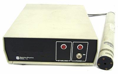
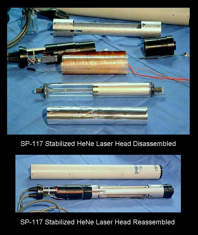
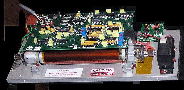
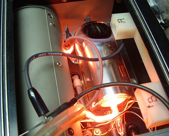
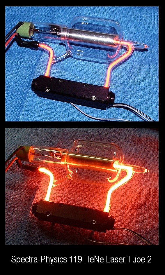
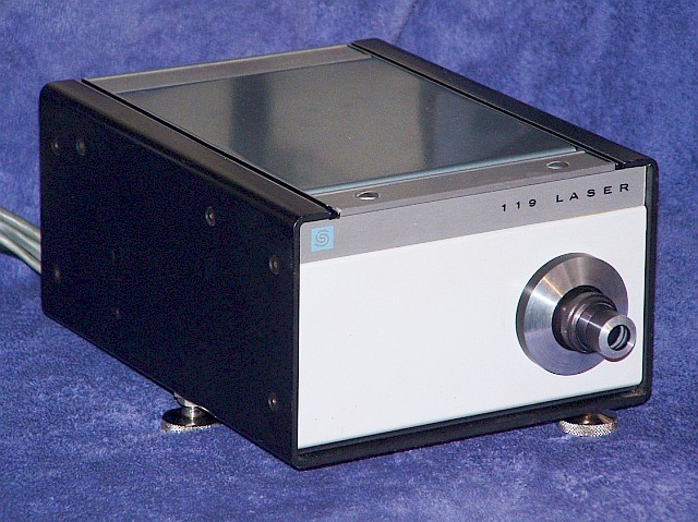
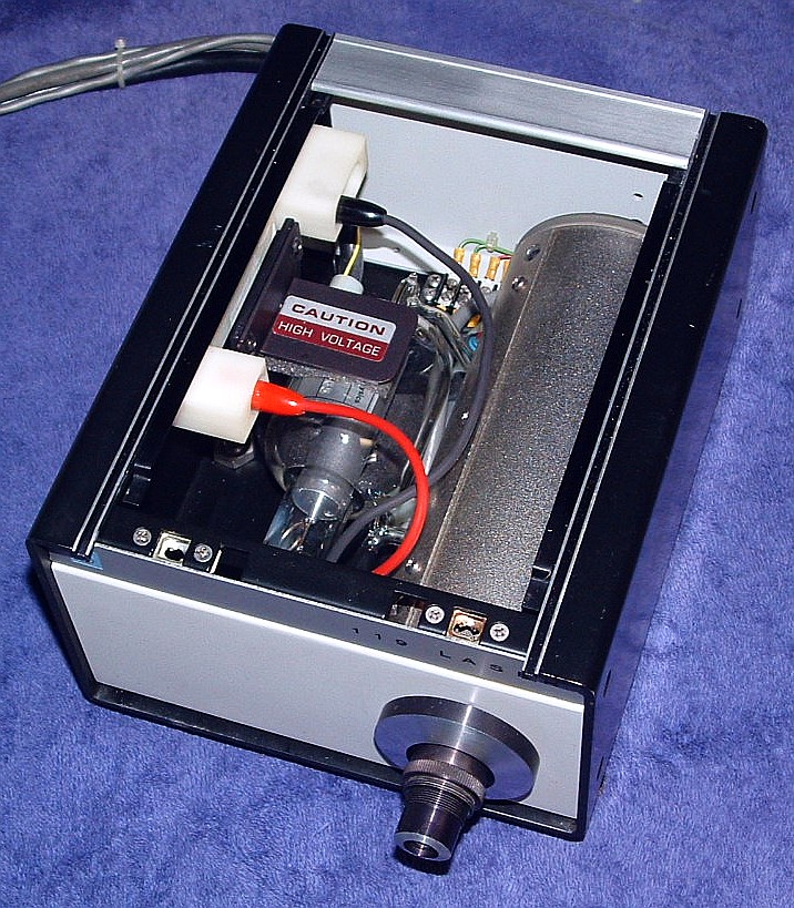
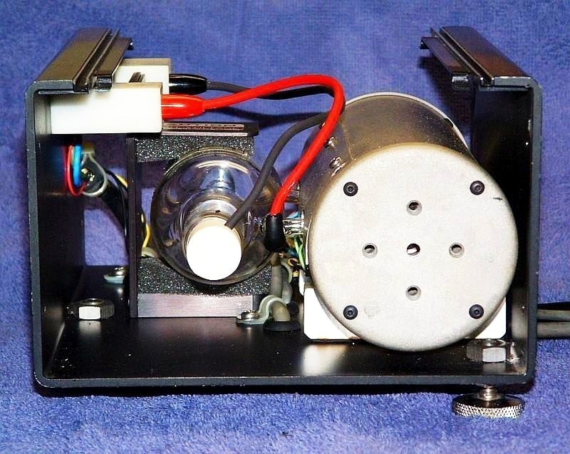
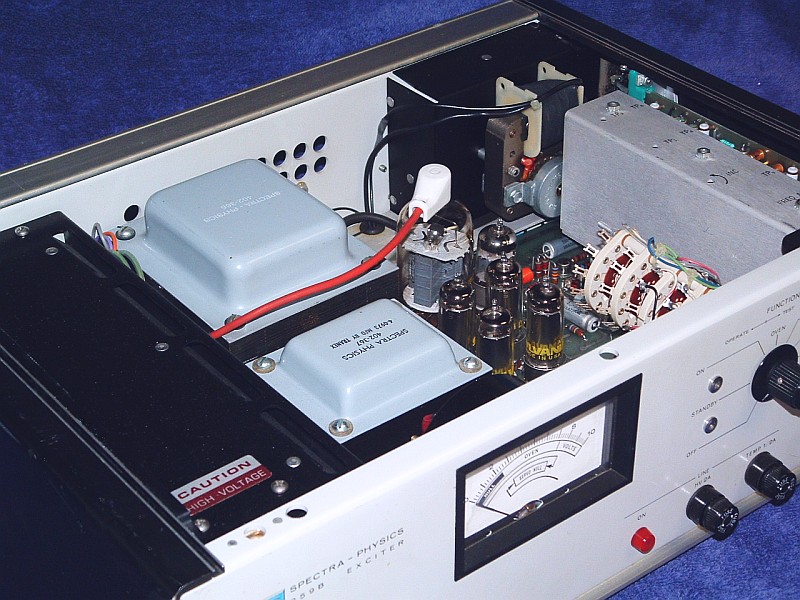
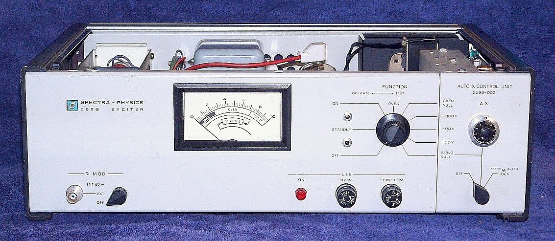
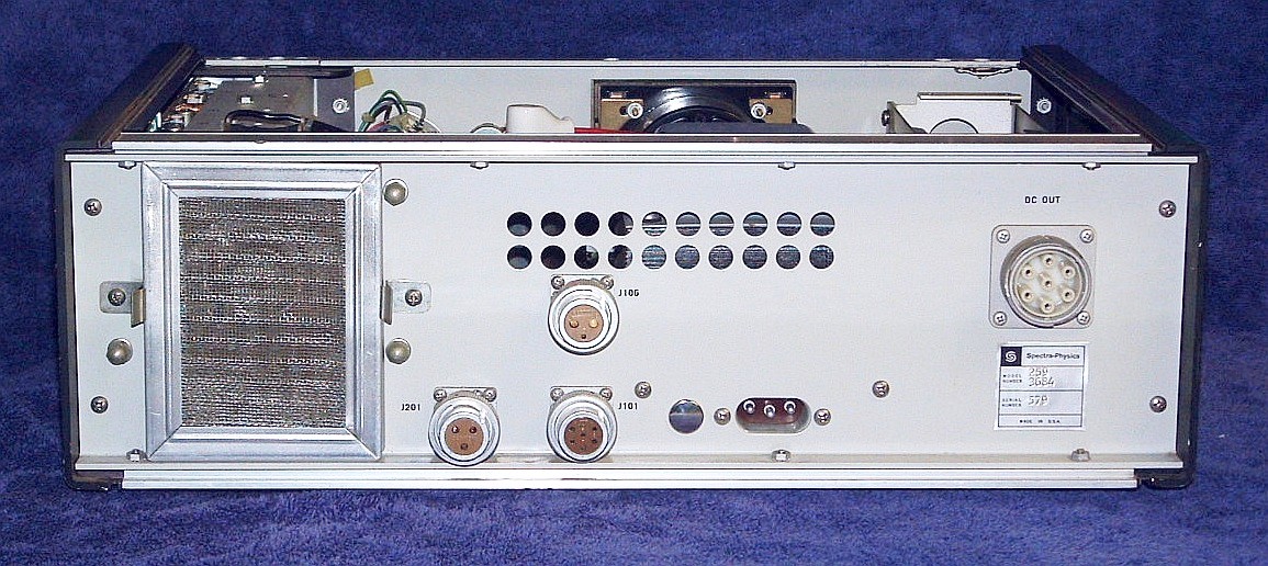
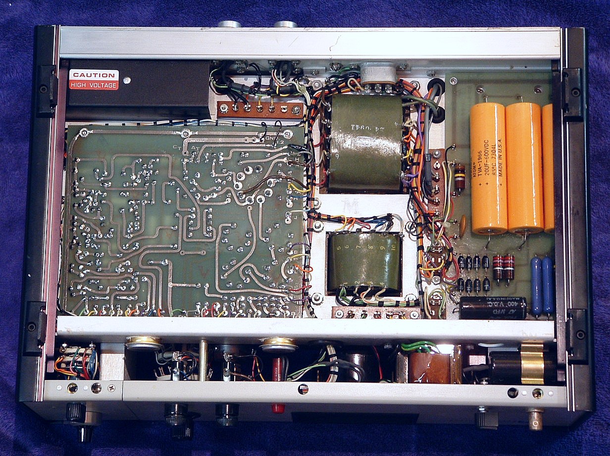
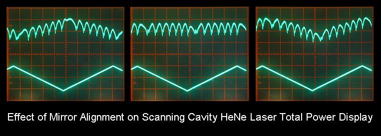
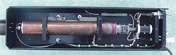
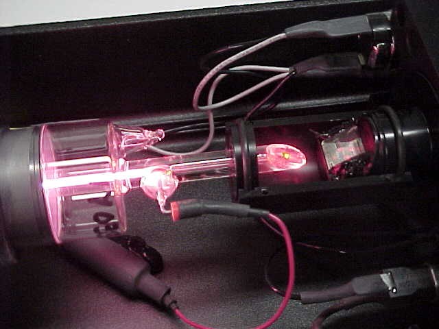
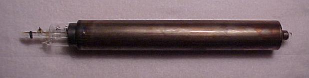
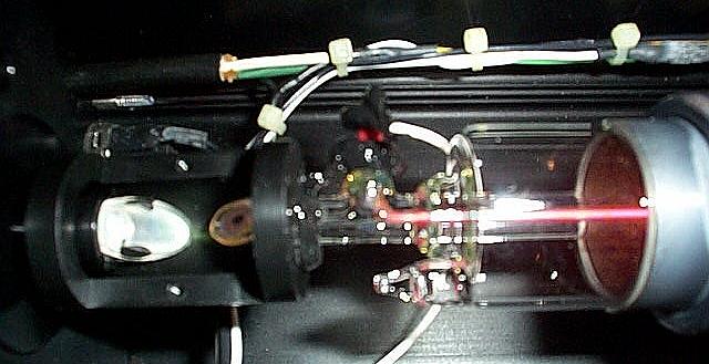
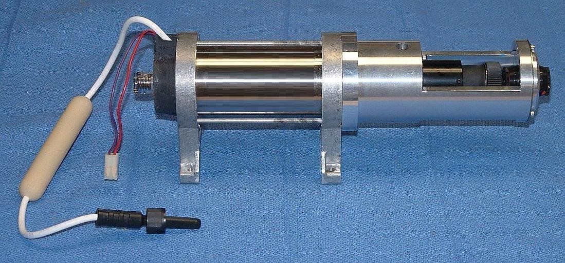
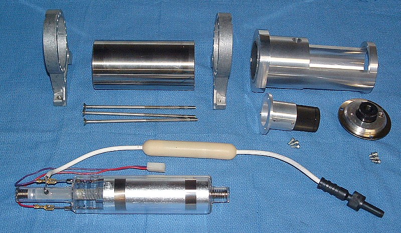
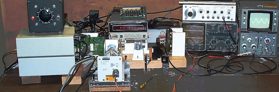
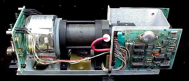
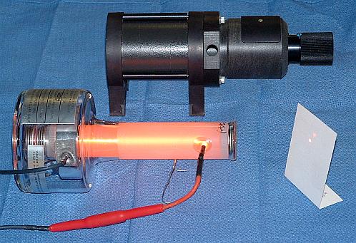
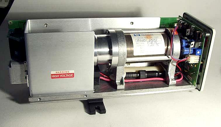
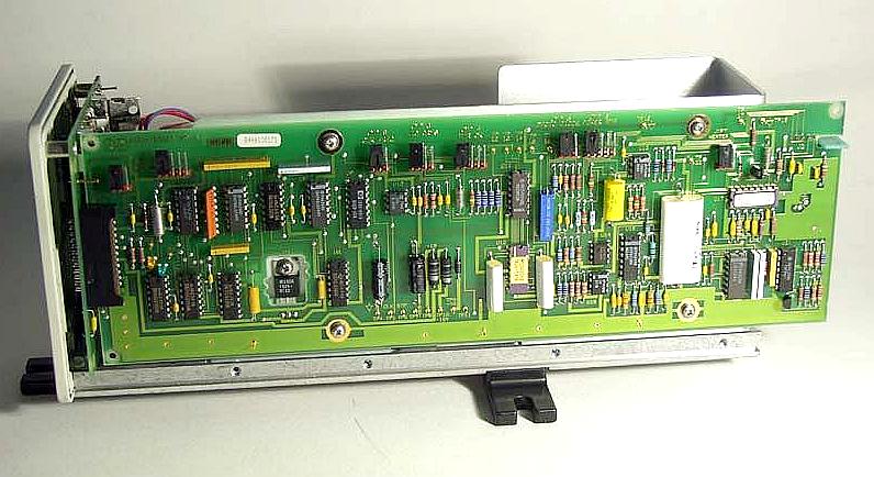
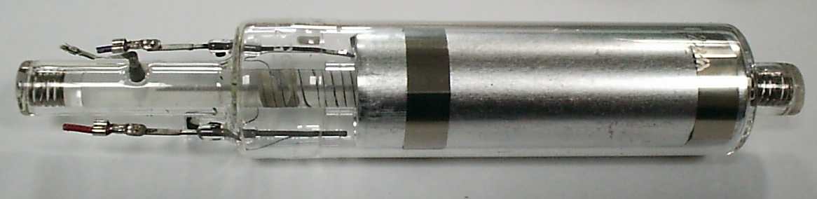
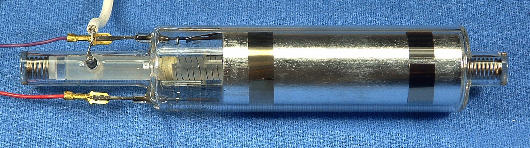
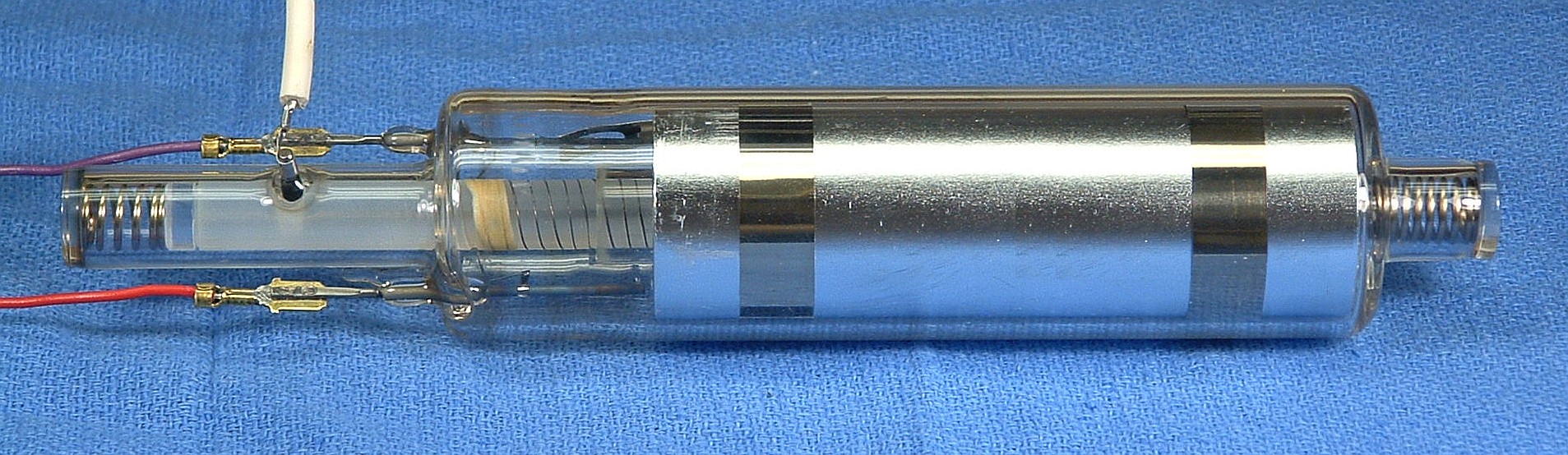
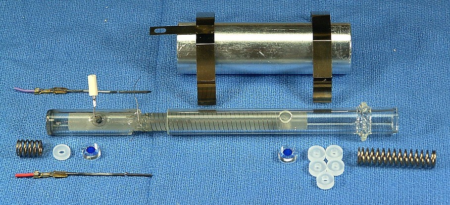
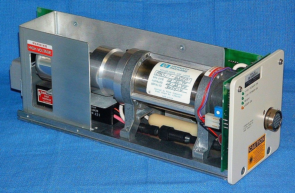
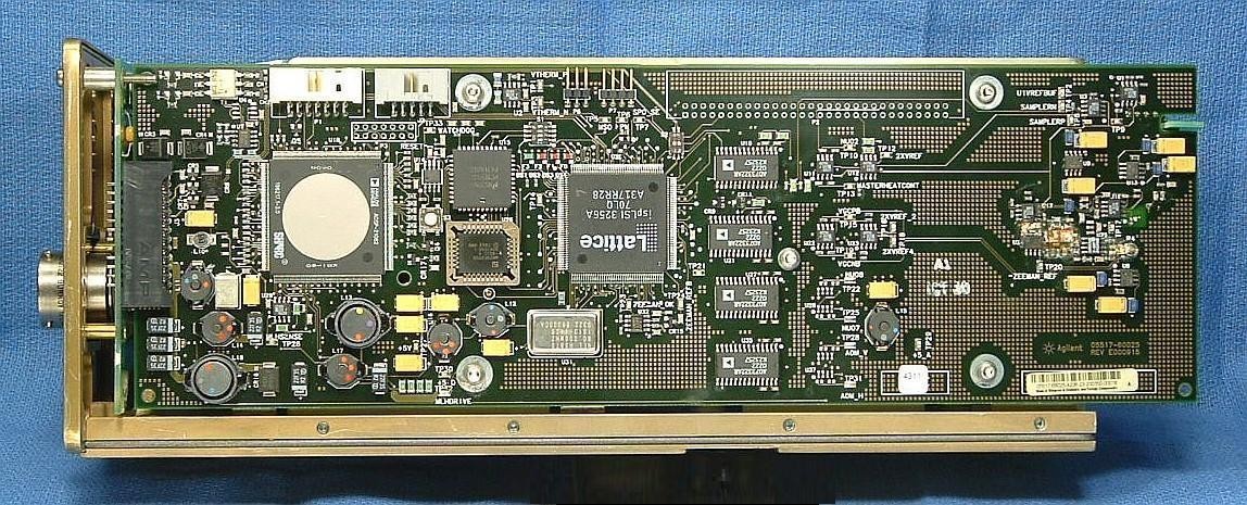
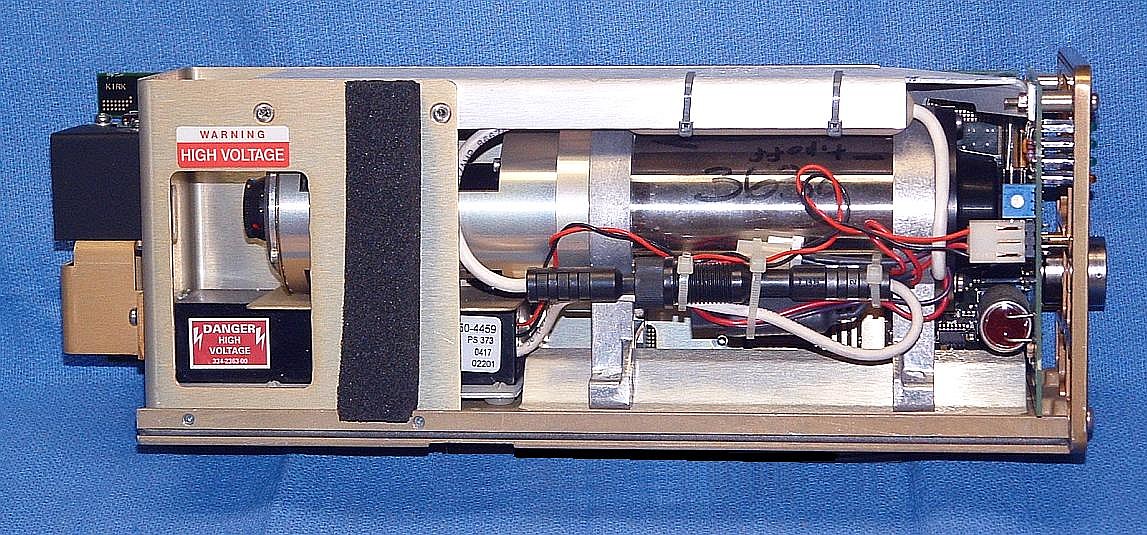
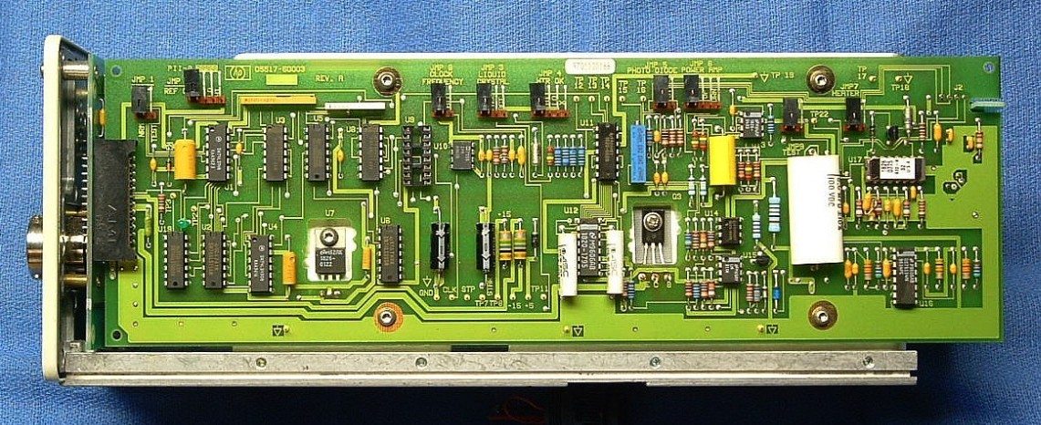
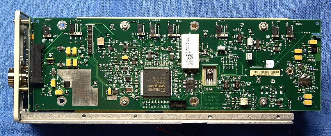
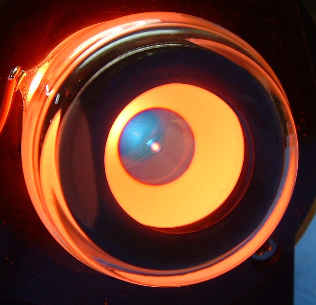
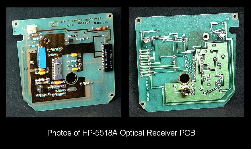
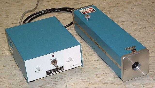
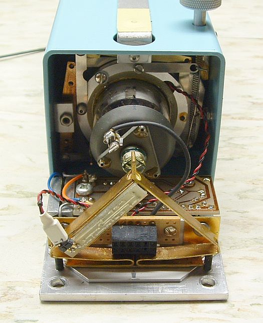
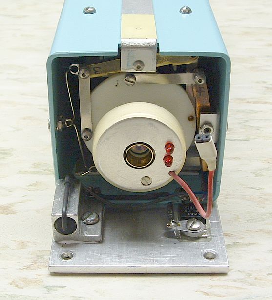
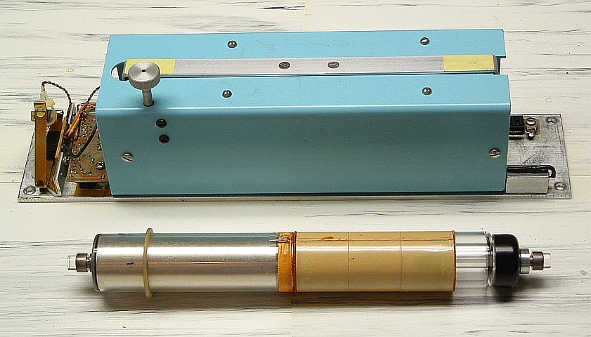
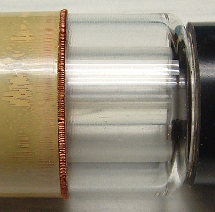
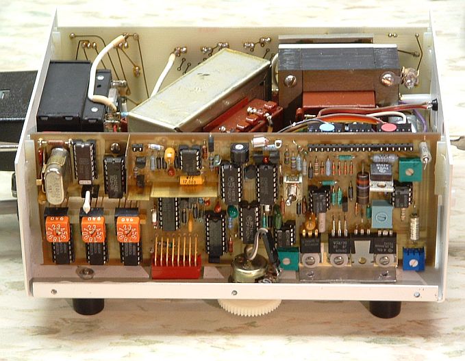
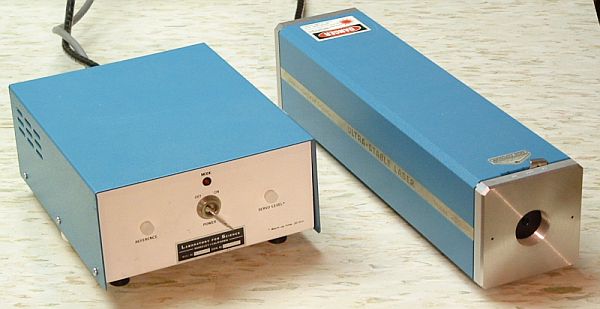
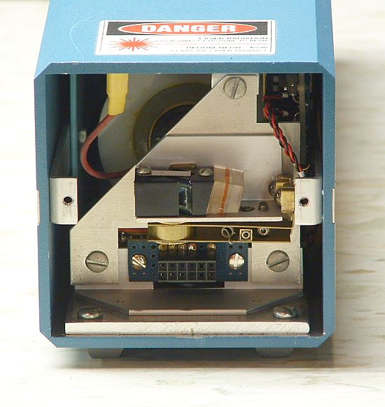
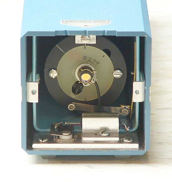
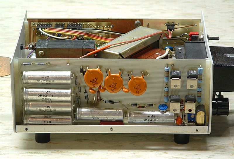
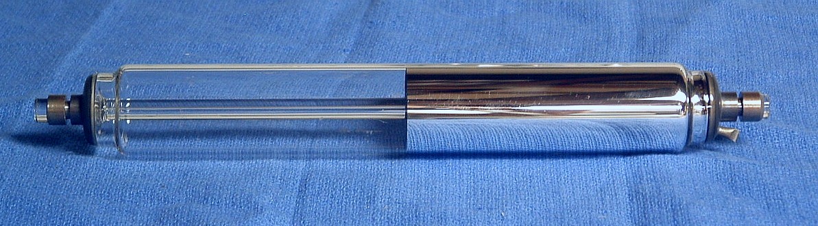
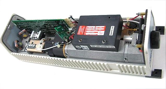
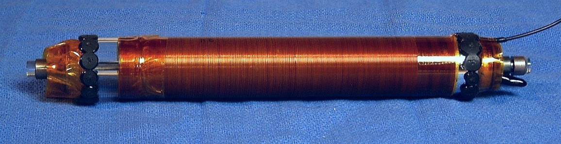
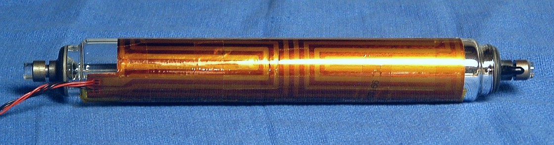
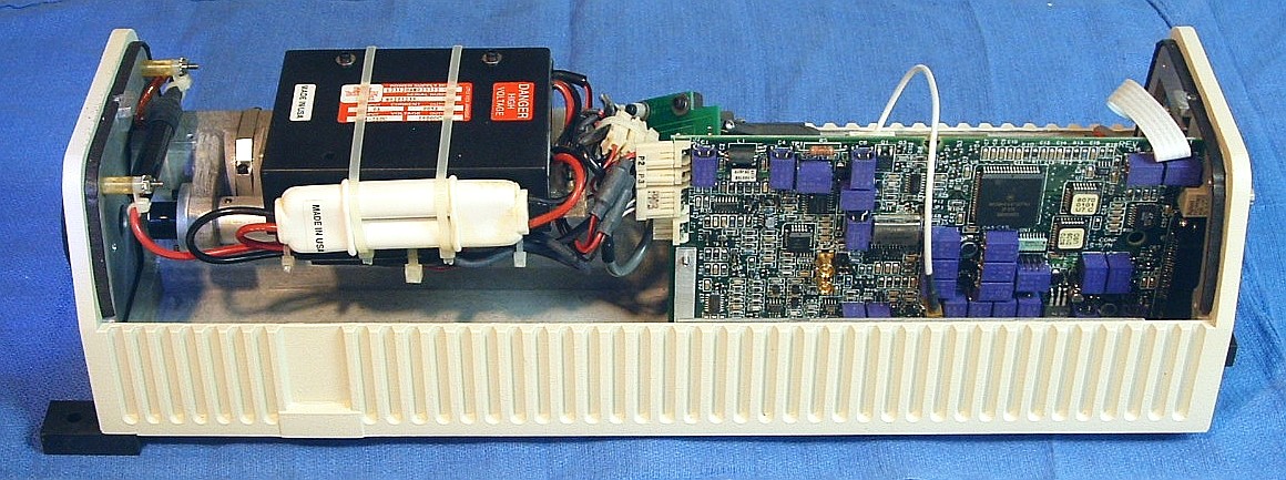
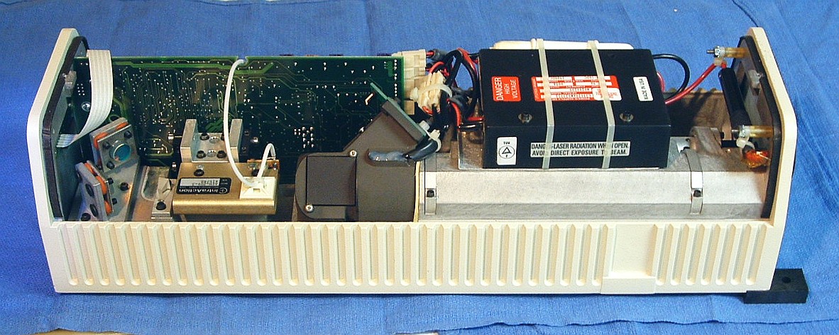
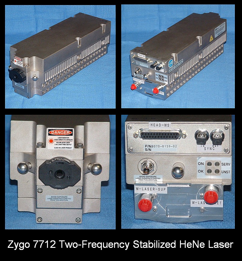
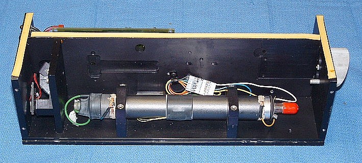
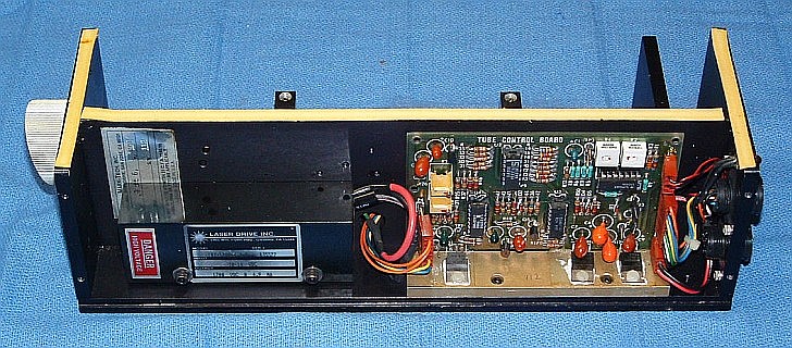
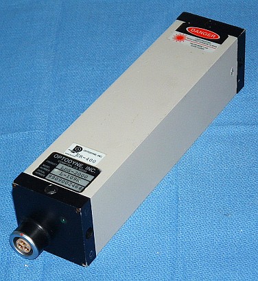
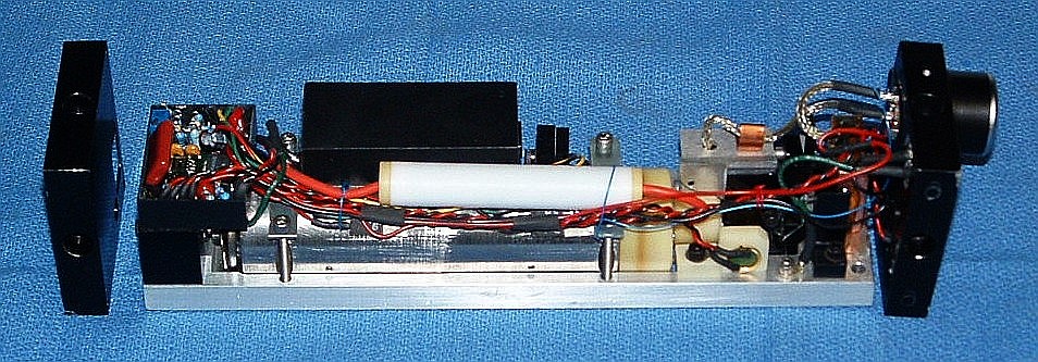
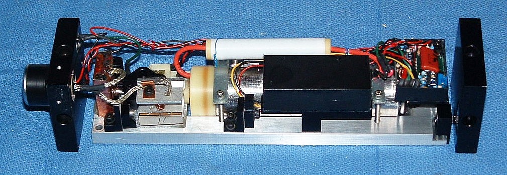
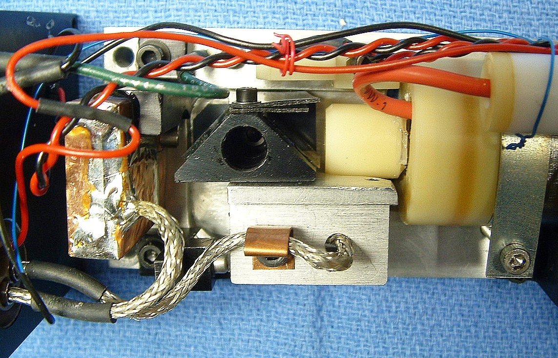
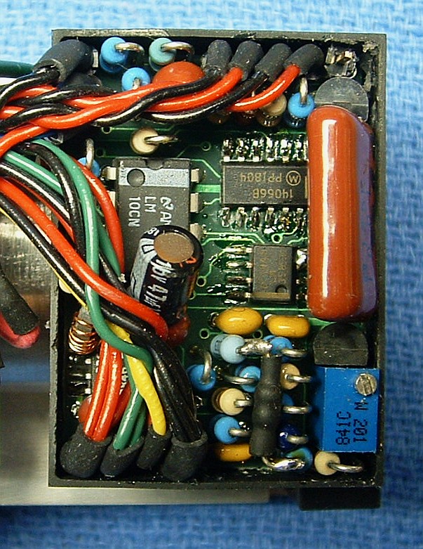