For contact info, please see the Sci.Electronics.Repair FAQ Email Links Page.
Copyright © 1994-2008
Reproduction of this document in whole or in part is permitted if both of the
following conditions are satisfied:
1.This notice is included in its entirety at the beginning.
All Rights Reserved
2.There is no charge except to cover the costs of copying.
DISCLAIMER
The power supplies for electronic flash and strobe equipment operate at extremely lethal voltage and current levels. The energy storage capacitors in even the smallest disposable camera flash operating from a 1.5 V AA battery can be deadly under the wrong conditions. Line powered strobes have added danger of high power at high voltage AND are often non-isolated (no power transformer. Do not attempt to troubleshoot, repair, or modify such equipment without understanding and following ALL of the relevant safety guidelines for high voltage and/or line connected electrical and electronic systems.
We will not be responsible for damage to equipment, your ego, county wide power outages, spontaneously generated mini (or larger) black holes, planetary disruptions, or personal injury or worse that may result from the use of this material.
PART I provides a basic description of the characteristics and principles of operation of electronic flash and related devices based on the xenon flashlamp. Especially important if you intent to be working inside this equipment is the SAFETY information. It is all too easy to electrocute yourself on the energy storage capacitors or line powered circuits.
PART II deals with troubleshooting and repair with emphasis on the kinds of electronic flash units found in photographic equipment - from tiny disposable cameras to high power studio 'speed lights'.
PART III provides information on the design of small to medium size electronic flashes and repeating strobes including basic design guidelines, shortening or lengthening flash duration, power supply component selection. There is a detailed discussion on retrofitting an old camera to use a modern electronic flash. And, there are a variety of circuits for repeating flashes, trigger circuits, inverters, and more.
PART IV provides over a dozen complete (well, very nearly complete, anyhow) schematics for electronic flash units from disposable cameras, external (Hot shoe or side mounted) strobes, higher performance line powered units, as well as repeating stroboscopes and even a timing light.
Note: Links to all the diagrams and photographs referenced from this document can be found in Sam's Strobe FAQ Files.
The single largest collection of hobbyist type xenon flash and strobe information can probably be found at the Don Klipstein's Lighting Technology Web Site which is a valuable resource for information relating to lighting technology in general and also includes additional articles dealing with strobe principles and design. Don's Xenon Flash and Strobe Page also includes a guaranteed late model version of Sam's Strobe FAQ.
A large collection of lighting and strobe related schematics and links can be found Tomi Engdahl's Lights and Electronics Page.
There are many other documents at the Sci.Electronics.Repair (S.E.R) FAQ Web site or one of its mirror sites which may be of use in the design, testing, and repair of strobe equipment. The Main Table of Contents (ToC) provides links to a variety of information on troubleshooting and repair of many types of equipment, general electronics, an assortment of schematics, over 1,000 technology links, and much more. Most of these documents are nicely formatted, indexed, and cross-referenced. (Silicon Sam's Technology Resource, which may be present at this site and others, usually contains slightly more recent versions of many of these same documents but most of those under the S.E.R FAQ Main ToC are easier to use and the actual content differences are likely to be minor.)
All modern electronic flash units (often called photographic strobes) are based on the same principles of operation whether of the subminiature variety in a disposable pocket camera, high quality 35 mm camera, compact separate hot shoe mounted unit, or the high power high performance unit found in a photo studio 'speed light'. All of these use the triggered discharge of an energy storage capacitor through a special flashlamp filled with xenon gas at low pressure to produce a very short burst of high intensity white light.
The typical electronic flash consists of four parts: (1) power supply, (2) energy storage capacitor, (3) a means of generating a trigger pulse, and (4) flashlamp, as shown below:
       HV+ o------/\/\-------------+----------------+
                Current            |         Anode _|_
     DC Power   Limiting       C1  |              | | |
      Supply    Resistor   Energy _|_+        FL1 |   ||
      (300 V              Storage ---       Xenon |   ||---- Trigger Pulse
      typical)          Capacitor  | -  Flashlamp |   ||
                                   |              | | |
                                   |       Cathode'-|-'
    HV Ret o-----------------------+----------------+
An electronic flash works as follows:
While details differ, everything from the flashing lights at your local disco to the flashlamps in monster pulsed lasers operate on essentially the same principles.
The energy of each flash is roughly equal to 1/2*C*V2 in watt-seconds (W-s) where V is the value of the energy storage capacitor's voltage and C is its capacitance. Not quite all of the energy in the capacitor is used but it is very close. The energy storage capacitor for pocket cameras is typically 100 to 400 uF at 330 V (charged to 300 V) with a typical flash energy of 10 W-s. For high power strobes, 1000s of uF at higher voltages are common with maximum flash energies of 100 W-s or more. Another important difference is in the cycle time. For pocket cameras it may be several seconds - or much longer as the batteries run down. For a studio 'speed light', fractional second cycle times are common.
Typical flash duration is a millisecond or less resulting in crystal clear stop action photographs of most moving subjects. However to capture really high speed motion like a the splash of a water droplet or a speeding rifle bullet flashes down to 1 millionth of a second or less are needed. These can be provided by specially designed strobe equipment but still based on principles very similar to those used in a pocket flash.
On cheap cameras (and probably some expensive ones as well) physical contacts on the shutter close the trigger circuit precisely when the shutter is wide open. Better designs use an SCR or other electronic switch so that no high voltage appears at the shutter contacts (or hot shoe connector of the flash unit) and contact deterioration due to high voltage sparking is avoided.
Note that for cameras with focal plane shutters, the maximum shutter speed setting that can be used (X-Sync) is typically limited to between 1/60 and 1/120 of a second. The reason is that for higher shutter speeds, the entire picture is not exposed simultaneously by the moving curtains of the focal plane mechanism. Rather, a slit with a width determined the by the effective shutter speed moves in front of the film plane. For example, with a shutter speed setting of 1/1000 of a second, a horizontally moving slit would need to be about 1/10 of an inch wide for a total travel time of 1/60 of a second to cover the entire 1.5 inch wide 35 mm frame. Since the flash duration is extremely short and much much less than the focal plane curtain travel time, only the film behind the slit would be exposed by an electronic flash. For shutter speed settings longer than the travel time, the entire frame is uncovered when the flash is triggered.
For complete schematics of both battery and AC line powered equipment, see the sections starting with: Schematics for Pocket Camera and Externally Mounted Compact Flash Units.
Red-eye reduction provides a means of providing a flash twice in rapid succession. The idea is that the pupils of the subjects' eyes close somewhat due to the first flash resulting in less red-eye - imaging of the inside of the eyeball - in the actual photograph.
This may be done by using the main flash but many cameras use a small, bright incandescent bulb to 'blind' the eyes when the shutter is pressed to meter, then it goes off and the flash preserves the 'closed' pupils. This approach works. Using the main flash would require sub-second recycle time which is not a problem if an energy conserving flash is used (see the section: Vivitar Auto/Thyristor 292 Energy Conserving Automatic Flash. However, it would add significant additional expense otherwise (as is the case with most cameras with built in electronic flash). A separate little bulb is effective and much cheaper.
Failure of red-eye reduction or the automatic exposure control circuits will probably require a schematic to troubleshoot unless tests for bad connections or shorted or open components identify specific problems. However, some of these use fairly simple circuits with mostly standard components and can be traced without too much difficulty. For red-eye in particular, It is also possible for that extra incandescent light bulb to be burnt out but good luck replacing it!
Remotely triggered 'fill flashes' use a photocell or photodiode to fire an SCR (or light activated SCR) which emulates the camera shutter switch closure for the flash unit being controlled. There is little to go wrong with these devices.
Cameras Underwater Flash Technical Primer has a summary of flash fundamentals is also be worth reading before delving deeper into this technology.
Automatic electronic flash units provide an optical feedback mechanism to sense the amount of light actually reaching the subject. The flash is then aborted in mid stride once the proper exposure has been made. This means that the flash duration will differ depending on exposure - typically from 1 ms at full power to 20 us or less at close range.
Inexpensive automatic flash units just short across the flashlamp with an SCR or second internal 'quench' tube (an internal small xenon tube that looks like an oversize neon indicator lamp) triggered by a photosensor. See the sections starting with: "Vivitar Auto 253 electronic flash circuit". With these units, the same amount of energy is used regardless of how much light is actually required and thus low and high intensity flashes drain the battery by the same amount - and require the same cycle time. The excess energy is wasted. Note that it is not the distance to the subject that matters but the amount of total light energy reflected back to the sensor. The travel time of the light has nothing to do with controlling exposure. True energy conserving flash units use only as much energy as needed and the batteries last much longer since most flash photographs do not require maximum power. Furthermore, when using low power flashes, the cycle time is effectively zero since the main energy storage capacitor does not discharge significantly. Therefore, multiple shots can be taken in rapid succession. See the section: Vivitar Auto/Thyristor 292 Energy Conserving Automatic Flash.
Many energy conserving flash units use a clever approach to avoid having to interrupt the 100 AMPS or more that may be flowing through the flashlamp. Like the non-energy conserving type, they bypass current around the flashlamp at the instant that the flash is to be terminated. But rather than dumping the energy to ground and wasting all of it, the current is diverted into a small capacitor. The voltage across the flashlamp drops to a low value just long enough for the flashlamp to revert to a non-conducting state. Only a small amount of energy is lost (that which goes into the bypass capacitor). More sophisticated units use something like a Gate TurnOff Thyristor (GTO) or high power Insulated Gate Bipolar Transistor (IGBT) to actually interrupt the flash discharge at the proper instant. These save virtually 100 percent of the energy and the circuitry is actually simpler, but the cost and availability of GTOs or IGBTs with the required peak surge rating of 100s of AMPS are a consideration in their design.
Although the high voltage inverter and actual flash tiggering circuitry is usually easy to trace, failure of the automatic exposure control circuit itself will probably require a schematic to troubleshoot unless tests for bad connections or shorted or open components identify specific problems. However, some of these use fairly simple circuits with mostly standard components and can be traced without too much difficulty though the compactness of modern flash units makes this somewhat more of a challenge. The most likely failures are still in the power circuits, not the control.
There are two potential hazards in dealing with the innards of electronic flash and other xenon strobe equipment:
High voltage with high energy storage is an instantly deadly combination. Treat all of these capacitors - even those in tiny pocket cameras with respect. Always confirm that they are discharged before even thinking about touching anything. On larger systems especially, install a shorting jumper after discharging just to be sure - capacitors have been known to recover a portion of their original charge without additional power input. Better to kill the power supply than yourself if you forget to remove it when powering up.
Reading and following these recommendations and heeding the warnings is especially important when working with high power strobes.
See the document: Safety Guidelines for High Voltage and/or Line Powered Equipment.
A working electronic flash or strobe may discharge its capacitors fairly quickly when it is shut off but most DO NOT do this. Furthermore, do not assume that triggering the flash fully discharges either the power supply filter or main energy storage capacitors fully - especially if it is a sophisticated automatic unit.
The main filter capacitors in the low voltage power supply may have bleeder resistors to drain their charge relatively quickly - but resistors can fail. Don't depend on them. For battery powered equipment in particular, efforts may have been made NOT to bleed the energy storage capacitor to conserve on battery power should another shot be desired at a future time. Some units even keep the flash fully charged when supposedly turned off!
The technique I recommend is to use a high wattage resistor of about 5 to 50 ohms/V of the working voltage of the capacitor. This will prevent the arc-welding associated with screwdriver discharge but will have a short enough time constant so that the capacitor will drop to a low voltage in at most a few seconds (dependent of course on the RC time constant and its original voltage).
Then check with a voltmeter to be double sure. Better yet, monitor while discharging.
Obviously, make sure that you are well insulated!
For the power supply filter capacitors or main energy storage capacitors, which might be 400 uF at 350 V, a 2 K ohm 25 W resistor would be suitable. RC=.8 second. 5RC=4 seconds. A lower wattage resistor (compared to that calculated from V^^2 / R) can be used since the total energy stored in the capacitor is not that great (but still potentially lethal).
The discharge tool and circuit described in the next two sections can be used to provide a visual indication of polarity and charge for TV, monitor, SMPS, power supply filter capacitors and small electronic flash energy storage capacitors, and microwave oven high voltage capacitors.
Reasons to use a resistor and not a screwdriver to discharge capacitors:
A suitable discharge tool for each of these applications can be made as quite easily. The capacitor discharge indicator circuit described below can be built into this tool to provide a visual display of polarity and charge (not really needed for CRTs as the discharge time constant is virtually instantaneous even with a multi-M ohm resistor.
Again, always double check with a reliable voltmeter or by shorting with an insulated screwdriver!
A visual indication of charge and polarity is provided from maximum input down to a few volts.
The total discharge time is approximately 1 second per 100 uF of capacitance (5RC with R = 2 K ohms).
Safe capability of this circuit with values shown is about 500 V and 1000 uF maximum. Adjust the component values for your particular application.
The following schematic is available as a PDF in Capacitor Discharge Indicator Circuit or in ASCII, below.
(Probe)
o-------+
 In 1   |
        /
        \    2 K, 25 W     Unmarked diodes are 1N400X (where X is 1-7)
        /                   or other general purpose silicon rectifiers.
        \
        |
        +-------+--------+
      __|__   __|__      |
      _\_/_   _/_\_      /
        |       |        \ 100 ohms
      __|__   __|__      /
      _\_/_   _/_\_      |
        |       |        +----------+
      __|__   __|__    __|__      __|__      Any general purpose LED type
      _\_/_   _/_\_    _\_/_ LED  _/_\_ LED   without an internal resistor.
        |       |        |    +     |    -   Use different colors to indicate
      __|__   __|__      +----------+         polarity if desired.
      _\_/_   _/_\_      |
 In 2   |       |        |
o-------+-------+--------+
(GND Clip)
The two sets of 4 diodes will maintain a nearly constant voltage drop of about
2.8-3 V across the LED+resistor as long as the input is greater than around
20 V. Note: this means that the brightness of the LED is NOT an indication
of the value of the voltage on the capacitor until it drops below about 20
volts. The brightness will then decrease until it cuts off totally at around
3 volts.
Safety note: always confirm discharge with a voltmeter before touching any high voltage capacitors!
If the rotation rate of the wheel is such that one spoke or slot goes by a given position in exactly 1/24th of a second, the wheel will appear stationary since successive images will be identical. If it is moving a bit faster than this it will appear to be moving forward slowly. However, if it is going a bit slower, then it will be appear to be turning backwards slowly. The shorter the exposure with respect to the total frame time, the sharper will be the apparent effect. The number of slots per second of perceived motion will be equal to the difference in frame rate and number of slots per second passing a given point. So, a roulette wheel rotating such that 23 slots are passing by per second captured on a 24 frame per second camera will appear to be moving backwards at 1 slot per second.
The same applies to the use of a strobe light to freeze repetitive motion like the rotation of a shaft. It is all a matter of the relative speed of the sampling (the movie, video or strobe) with respect to an object which is periodic like a roulette or wagon wheel.
You can perform a simple experiment: run an electric fan under a fluorescent lamp (one with an ordinary magnetic ballest). The light from such a lamp is not continuous but pulses 120 times per second. Watch for stationary or slowly rotating blade patterns as the fan speeds up and slows down. See if you can compute the speed of the fan from this behavior.
Just for funsies, I decided to see how much torture I could inflict on the flashlamp and energy storage capacitor from one of those little Kodak cameras. The tube was 1.2" long, in a metalized plastic reflector, with a thin metal backing to hold it in. The capacitor was 120 uf, 330 V. I hooked it up to my inverter (12 V->300 V at high current) and fired 'er up! Pop, pop, pop, pop, pop, pop, pop, (turn up trigger oscillator frequency) popopopopopopopopopopopop! It was firing about 30 or 40 times a second; it appeared as it was constantly on! I turned it down to about 15 flashes a second, and let it run. First thing I noticed was that wonderful scent of melting acrylic. Then, I noticed that the tube was kind of skewed in the reflector. The plastic was in full smoke-mode by this point. Still, the tube kept firing! (Let's see: 5 W-s times 15 flashes per second is 75 W average power, not bad for an itty bitty tube --- sam).
I left it on a bit more, and the plastic really started the smoke-signals! I noticed that one electrode was glowing cherry red. Even after all this torture, it kept going! The smoke was getting too much, so I hit the 'off' on my inverter. A few more gouts of smoke, and the little fire I created was extinguished. I let it cool down and then I examined the damage. The reflector was totaled; the tube had all but melted clean through. When I touched it, the little metal plate popped off.
On closer examination, the tube appeared to be in good shape. I couldn't see any visible damage to either the electrodes, or the glass seals. A quick test reveals that the tube still functions. As a side note, the storage capacitor got quite hot; probably around 35 degrees C. All in all, an interesting test, I must say. The next will involve connecting up a normal NE2 neon bulb and observing the results of high voltage and high current on it. I suspect it will be quite spectacular, so I'm taking precautions - It will be performed in a proper enclosure, so if the neon decides to really go 'pop', it won't do any damage.
I used to design stage-effects, and played some time with strobes. Built a number, from 750 W-s at high rates to 22,500 W-s single flash. Philips makes xenon lamps, designed for photographic use - they are not flashtubes but burn continually - so using them as flashtube shortens their life span (assuming you increase power). They are expensive, from $250 for the smallest to $1,100 for the biggest.
For caps for the smaller (20 to 100 W-s) strobes, I used a huge array of MKT motor-caps. 10 uF at 630V is cheap, a few dollars, and building an array of these is not too hard. These caps are screw-mount, and you can just fill a board with them, and switch them in parallel. Keeps the ESR low, which is a requirement.
The monsters used larger caps, 680 uF each. My boss often visited executory sales and bought components and machinery. These caps (he had a number of crates full of them) sat on the shelves for a year before I decided to do something with them. Beautiful Siemens stuff. Very low ESR, large cap. Nevertheless, I did say "huge array" which was exactly that. Two boards (one for each set of lamps) filled with them, each board 1 by 1.5 meters, which dictated the size of the case. As I remember these caps were about 5 centimeters diameter, and something like 12 centimeters high, so - guessing - you could stack around 280 of them on a board, which sounds right.
All problems I had related to heat. The 750 and 1500 W-s models had a habit of melting their main wire. On typical stages one uses a lot of extension-wires, and its power consumption could be high enough to heat the extension to the point the insulation came dripping off, without blowing a fuse. Had to lower the amount of energy per flash at higher rates. The protective window in front was another problem area. Poly-carbonate covers work fine, but a single fingerprint absorbs enough IR to melt a hole in the cover. Glass won't melt, but shatters if dirty. Don't allow anything near it. Colored paper will catch fire within seconds, at max rate. Always use it to flash at a wall, never let the public look into such a bright flash.
The biggest used four larger tubes, flashing two by two, but charge-times were too long to make it usable as a real strobe. It was used to flash the ceiling of a large stadium. I considered it to be useless. I never solved the problems it had, like eating its eight, expensive, diodes (>$40 each) for lunch. It sucked dips in the mains, big enough to cause digital equipment to fail. Imagine all the effects of the audio-boys resetting after each flash. I kept it running for a few months, but when the edges of the window caught fire I scrapped it. I modified one off the triggers for the small strobe (750 and 1500 w-S) to allow multiple units.
I found a note in the same binder with a capacitor-free design for a strobe. The smallest Xenon tube made by Philips has a burning voltage low enough to start it on 220V. With a suitable choke and a diode in series it will burn - after ignition - for the rest of the half-cycle. The diode makes sure it dies when the polarity reverses. (Residual ionization will make it re-ignite without the diode) The choke will keep it from aggravating the utility-companies. I wonder if anyone knows a trick to enhance ionization. Fully ionized it has a burning-voltage of 50 Volts, but even after the 4 kV pulse it needs 200 Volts to get started. Only tricks I know are the 'normal' starter-pulse, microwave pulses, radioactivity and laser-pulses. Only the first one is acceptable with audiences around. It probably won't work with 110 V mains.
(From: Tomi H. Engdahl (then@cc.hut.fi).)
A friend of mine has around a 3 kW disco stroboscope. (It is really 3 kW as it blows a 230 V, 10 A fuse at full power. And you can guess that it is quite bright!) That stroboscope seems to be taking quite heavy (few tens of amperes) of current for one half wave when it flashes. The firing angle is controlled by the internal brightness control (dimmer).
What it looked inside on quick glance it seemed to have a heavy thyristor, rectifier, heavy line filter, one coil in series with the tube, the tube itself, and the triggering electronics.
(From: Sam.)
On 110 VAC you're out of luck if no caps are allowed and you don't want to use a stepup transformer. In any case, what you end up with is more of an arc lamp than a flashlamp since the current is limited to a few amps as opposed to 10s or 100s of A for even a tiny strobe.
WARNING: Defibrillators are at least as good at stopping beating hearts as restarting misbehaving ones. The charge in their energy storage capacitor (typically 300 to 400 Joules) is enough to kill a half dozen healthy adults instantly. The operating voltage (up to 5 kV) doesn't respect common wire insulation and can jump 1/4" or more in air. There are no second chances.
(From: Steve Roberts (osteven@akrobiz.com).)
Older defibrillators are now showing up as inexpensive surplus because their ancient edmark waveform is being replaced with newer computer controlled biphasic waveforms.
So what do you get in a typical edmark waveform defibrillator:
Notes: The relay is usually a 5 kV 50 A DPDT which has a short across one set of contacts to protect the patient. The other set of contacts goes to the capacitor common leads and to the patient via the paddles. So, presto! - apply 12 volts to the relay and you get up to 360 joules dumped into the victim or patient via the inductor to control the waveform. A patient's chest is assumed to be about 50 ohms impedance via the conductive cream to the paddles so the test circuit monitors what happens when the second smaller relay dumps the cap into the 50 ohm air cooled test resistor. The cap is also dumped during power-down.
I can't overstress the absolute need for safety when handling a 33 uF 5 kV capacitor. Newer defibrillators have a MOSFET H-bridge for bipolar switching and only go to two kV with smaller caps.
(From: Don Klipstein (don@misty.com).)
I actually busted some smaller flashtubes in a cup of vegetable oil to get an idea of the xenon pressure! In the Radio Shack U-shaped tubes, the pressure is about 80 Torr. In a smaller cheap linear tube with the electrodes 19 mm. apart, the pressure is about 180 Torr. In at least one version of the tiny tubes often used in cheap and disposable cameras, the pressure is about 450 to 500 Torr. Most other small camera flashtubes are 100 to 300 Torr.
In many medium and large flashtubes, the pressure seems to be around 80 Torr, except one I have seems to have a little less - maybe 60 Torr. This was for three different professional photoflash tubes, a larger version of the popular U-shaped strobe tube, and a large photocopier flashtube. I estimated the pressure in these by passing a few milliamps through them from a neon sign transformer (operated at reduced voltage) and commparing the appearance of the discharge to that in tubes of known pressue.
Larger photographic flashtubes - mostly around 80 to 200 Torr:
EG&G, Electro-Optics Division 35 Congress St Salem MA uses a standard pressure of 450 Torr in their superduper linear flashtubes, but won't hesitate to use a custom pressure at customer's request.
"I had an interesting idea. Get a small (2 watt) fluorescent tube, wrap several turns of wire round it, connect ends of tube to xenon strobe outputs, connect wire to HV trigger connection, switch it on. As far as I can tell, this would make one hell of a bright strobe! Any ideas???"Depending on the voltage and size of the tube, you may not need trigger - it will break down at lower voltage than xenon tube. For your 2 W tube, this is a certainty.
It will also only likely work for one or at most a few flashes unless you use a much smaller capacitor. What happens is the filaments disintegrate. Fluorescent tubes are NOT designed for the high peak current of a strobe type circuit with a large energy storage capacitor. Go much beyond their normal ratings of a few hundred mA and they will fail.
Been there, done that. I once powered an 8 foot fluorescent tube from a six volt lantern battery pulse circuit and stepup transformer - and even such a large tube was destroyed after a few flashes. But the flashes WERE pretty bright. :-)
(From: Don Klipstein (don@misty.com).)
It is not as bright as xenon. Also, triggering characteristics will change as strobe duty changes the condition of the electrodes, also as temperature changes and mercury vapor concentration changes. I've tried it - the fluorescent tube changes too much with temperature and past history of strobe use.
One more thing: A strobing fluorescent tube is more conductive than a xenon tube, which means more of the energy stored in the energy storage capacitor is used to heat the capacitor, and less is dissipated in the tube. But enough is dissipated into the tube to beat up the electrodes!
(From: Craig Douglas (blackspear@hotmail.com).)
You can very successfully flash banks of fluorescent lamps by running a continuous low current through the lamps and increasing the current (the lamps appear off, but are actually still lit). This works well in the electric sign industry.
The same principle is used to flash standard incandescent bulbs, without the bulbs blowing continually. It is the spike in initial power that blows the filament, running a low current continually through to keep the filament warm minimizes stress on the filament which stops it from blowing.
(From: Sam.)
It should be noted that this will not increase lamp life significantly in normal operation but may extend it by a few percent.
Mouser stocks a few xenon flashlamps and trigger transformers suitable for both small and medium power strobes.
A flashtube, trigger coil, and a more complete camera flash assembly are listed in their catalog.
Some strobe kits, flashtubes, reflectors, flashtube-reflector combos, a trigger coil, a quench tube (!!), two different inverter transformers, and two complete strobe schematics, one of which is a 12 volt strobe using one of these transformers.
The also sell small flashtubes by the bushel :-) about 1.2 inches long (~30 mm) by .15 inch (~3.5 mm) diameter. These cost 49 cents each, or 100 for $25. So, if you are planning on building your own New Year's Times Square celebration sphere, these may be ideal! These were offered in 1996 and may no longer be available but should be worth an inquiry.
High power capacitors (like 450 uf at 500 volts) and other strobe parts may be had though the list of strobe service centers at Lumedyne.
However, it should be remembered that they are repair centers and do not normally sell parts at retail. I have ordered a capacitor like the one mentioned above from one them at a cost of $26.00 plus $3.50 S&H.
(What this means is that (1) their prices may be quite high and (2) they may not be eager to sell to the public. --- sam)
The original Strobotac flashtubes were made by EG&G Optoelectronics. They used a FX6-A. I believe they now supply a FX7-A as a replacement. You can reach them at 1-800-950-3441.
You might also try Quad Tech, which still manufactures the General Radio 1531AB, and other General Radio stroboscopes. They can supply spare parts. You can reach them at 1-800-253-1230.
The going rate for a typical cheap flash camera is generally $.50 to $1 at a garage sale or flea market. While these may in fact still work, they often use 110 size film so you won't feel too badly about gutting them for the flash unit or its parts.
Although in principle the capacitor may deform after a long period of non-use, I have yet to see any real trouble having picked up over 2 dozen cameras and strobes from these sources. None of these have had any actual defective components (though a couple had bad connections or broken wires). My last acquisition was a completely functional variable rate stroboscope for $2.
(From: Scott Johnston (sj@thor.iac.net).)
Complete working strobe circuits are available for *free* at photo developing places (not K-mart, but the expensive places that actually do the developing in-house). When they develop film from those cheap weekend disposable cameras (you know, the kind that are made out of plastic and cardboard?), they rip out the film and throw away the camera housing. The disposables with flashes have a complete xenon strobe circuit (triggered by a tiny little switch on wire leads) powered by a single AA (1.5v) alkaline battery. Recently, I called the local photo developer, asked if they could save some of the kind with flashes, and a few days later I picked up a pile of 12 complete flash units, with almost unused AA batteries in all of them! Really fun, although I discovered quickly that the capacitors in those things don't have bleeder resistors...
(From: Alfred C. Erpel (aerpel@ptd.net).)
I was picking up my Halloween party photos from the 1 Hour Photo place at my local drug store and I noticed a trash box full of thrown out single use cameras, empty 35mm spools and plastic containers. I asked if I could have the entire box.
When I got home I found I had 27 cameras with usable flash units and most of the AA batteries were still good. My wife got the plastic containers for her Girl Scouts crafts. The inside of used Kodak film canisters contains a nifty spool which may make a useful bobbin for some types of coils.
Watch out for residual charge on the flash capacitor when you disassemble these! Also, observe the mechanics carefully because, although I'm not certain about this yet, it seems that some of the cameras are designed to purposely disable the flash circuitry by mechanically breaking an existing connection when the board is removed. Obviously this could be restored if you see where it is.
No doubt some places won't give you their trash (afraid of the potential for liability), but it can't hurt to ask.
Information is available for driving flashlamps (and other topics) in the Perkin Elmer (formerly EG&G) Technical Library. However, much of the product and technical info that used to be on the EG&G Web site is no longer present. but this material is available on the Perkin Elmer CDROM, which includes complete product specifications and technical papers. The CDROM is accessed using your normal Web browser. Some flashlamp info is also available at Polytec PI France - Department Electro-Optique - EG<G.
General technical information on flashlamps and arc lamps may be accessed via their Download Page.
Some very complete technical notes on driving and triggering of flashlamps has been published by ILC Technology (now part of Perkin Elmer). Some of these include:
These were originally published around 1986 so there may be newer versions. As far as I know, they are not currently on-line but should be available in print by contacting ILC.
A variety of failures are possible with electronic flash units. Much of the circuitry is similar for battery/AC adapter and line powered units but the power supplies in particular do differ substantially.
Most common problems are likely to be failures of the power supply, bad connections, dried up or deformed energy storage or other electrolytic capacitor(s), and physical damage to the to the flashtube or other components.
Symptoms: unit is totally dead, intermittent, or has excessively long cycle time.
Test and/or replace batteries. Determine if batteries are being charged. Check continuity of power switch or interlock and inspect for corroded battery contacts and bad connections or cold solder joints on the circuit board.
Symptoms: unit is totally dead or loads down power source when switched on (or at all times with some compact cameras). No high pitched audible whine when charging the capacitor. Regulator failure may result in excess voltage on the flashtube and spontaneous triggering or failure of the energy storage capacitor or other components.
Test main chopper transistor for shorts and opens. This is the most likely failure. There is no easy way to test the transformer and the other components rarely fail. Check for bad connections.
Symptoms: unit is totally dead, operates poorly, catches fire, or blows up. Spontaneous triggering may be the result of a regulator failure or running on a too high line voltage (if the unit survives).
Test outlet with a lamp or circuit tester. Check line voltage setting on flash unit (if it is not too late!).
Symptoms: unit is totally dead or fuse blows. Excessive cycle time.
Test fuse. If blown check for shorted components like rectifiers and capacitors in the power supply. If fuse is ok, test continuity of line cord, power switch, and other input components and wiring. Check rectifiers for opens and the capacitors for opens or reduced value.
Symptoms: reduced light output and unusually short cycle time may indicate a dried up capacitor. Heavy loading of power source with low frequency or weak audible whine may indicate a shorted capacitor. Excessively long cycle time may mean that the capacitor has too much leakage or needs to be reformed.
Test for shorts and value. Substitute another capacitor of similar or smaller uF rating and at least equal voltage rating if available.
Cycling the unit at full power several times should reform a capacitor that has deteriorated due to lack of use. If the flash intensity and cycle time do not return to normal after a dozen or so full intensity flashes, the capacitor may need to be replaced or there may be some other problem with the power supply.
Symptoms: energy storage capacitor charges as indicated by the audible inverter whine changing frequency increasing in pitch until ready light comes on (if it does) but pressing shutter release or manual test button has no effect. Spontaneous triggering may be a result of a component breaking down or an intermittent short circuit.
Test for voltage on the trigger capacitor and continuity of the trigger transformer windings. Confirm that the energy storage capacitor is indeed fully charged with a voltmeter.
Symptoms: flash works normally but no indication from ready light. Or, ready light on all the time or prematurely.
Test for voltage on the LED or neon bulb and work backwards to its voltage supply - either the trigger or energy storage capacitor or inverter trans- former. In the latter case (where load detection is used instead of simple voltage monitoring) there may be AC across the lamp so a DC measurement may be deceptive.)
Symptoms: manual test button will fire flash but shutter release has no effect.
Test for shutter contact closure, clean hot shoe contacts (if relevant), inspect and test for bad connections, test or swap cable, clean shutter contacts (right, good luck). Try an alternate way of triggering the flash like a cable instead of a the hot shoe.
Symptoms: energy storage and trigger capacitors charges to proper voltage but the manual test button does not fire the flash even though you can hear the tick that indicates that the trigger circuit is discharging.
Some xenon tubes have "getters", which are silver or dark silver coatings of a highly reactive metal, deposited on the inner surface of the flashtube at one or sometimes both ends. Less frequently, a getter may be found on a metal surface such as one of the electrodes inside the tube, but not on the tubing inner surface. The getter "gets" any traces of air or water vapor in the flashtube. If a flashtube with a getter is broken or leaky, the getter will be corroded into a powdery gray-white form. If you know there is a getter and it is corroded badly, the flashtube is no good. Please note that unrelated glass discoloration or staining that resembles corroded getters can occur in a heavily used or moderately abused flashtube that still works.
Inspect the flashtube for physical damage. Substitute another similar or somewhat larger (but not smaller) flashtube. A neon bulb can be put across the trigger transformer output and ground to see if it flashes when you press the manual test button shutter release. This won't determine if the trigger voltage is high enough but will provide an indication that most of the trigger circuitry is operating.
For rechargeable units, try charging for the recommended time (24 hours if you don't know what it is). Then, check the battery voltage. If it does not indicate full charge (roughly 1.2 x n for NiCds, 2 x n for lead-acid where n is the number of cells), then the battery is likely expired and will need to be replaced.
Even for testing, don't just remove the bad rechargeable batteries - replace them. They may be required to provide filtering for the power supply even when running off the AC line or adapter.
For units with disposable batteries, of course try a fresh set but first thoroughly clean the battery contacts.
See the sections on batteries.
The energy storage capacitor will tend to 'deform' resulting in high leakage and reduced capacity after long non-use. However, you should still be able to hear the high pitched whine of the inverter.
Where the unit shows no sign of life on batteries or AC, check for dirty switch contacts and bad internal connections. Electrolytic capacitors in the power supply and inverter may have deteriorated as well.
If the unit simply takes a long time to charge, cycling it a dozen times should restore an energy storage capacitor that is has deformed but is salvageable. This is probably safe for the energy storage capacitor as the power source is current limited. However, there is no way of telling if continuous operation with the excessive load of the leaky energy storage capacitor will overheat power supply or inverter components.
When a flashlamp fails, it may do so quietly or with a bang.
Generally, only laser pump flashlamps or similar ones with a lot of flash energy for their size will likely die spectacularly. When lower power flashlamps such as those used in small to medium size photographic strobes crack, they tend to stay in one piece or sometimes break apart surprisingly quietly.
Line voltage transformers: Most AC line powered flash units don't have any transformer so this isn't general a problem. For those that do (higher speed or other special types of strobes), it shouldn't be difficult to match up the secondary voltage and find a standard replacement that will be acceptable. These may be cobbled together from the power transformers for vacuum tube equipment (yes, they can still be found), small isolation transformers with multiple windings, and possibly the addition of some additional lower voltage windings in buck or boost phase to adjust the output voltage.
For safety reasons, I don't recommend attempting to repair transformers connected to the AC line, though this may be a possibility if all else fails.
Inverter transformers in battery powered flash units:
There is virtually no chance of successfully repairing any of these. The secondary winding uses wire so fine that it's almost impossible to even handle it. With a decent coil winding machine, a new spool of #45 or so wire, proper insulating tape (these are wound in 10 to 20 separate layers), and a few days of patience, it can be done but doesn't rank up there on my "fun things to do list". :) Furthermore, it's almost certain the core got destroyed in attempts to get at the windings. Thus, replacement is the only viable option.
There is NO chance of getting one of these from an electronics distributor as they are all custom. Since it's almost a certainty that the original manufacturer will have little interest in selling you a new one, salvage from other flash units is the best hope. These can be $1 garage sale specials (other 35 mm, 126, or similar cameras), disposable camera flashes, or shoe mounted units, depending on the physical size and energy (guide number) rating of your broken flash. The main problem will be the number of turns on the primary. If you can match those up by adding or removing turns to your replacement, there is a good chance it will work since they all seem to have roughly the same number of secondary turns (probably around 1,600 to 2,000). Even if the primary is buried, you can still add turns on top of the secondary in the appropriate direction to adjust the total net turns. Once its running, adding or removing an additional turn or two may be needed to tweak the output voltage.
Another option is to transplant the entire inverter if one can be found that operates on the same input (battery) voltage. I've done this successfully. without problems. See "Repair Brief #100: Minox ME1 Electronic Flash for Minox B Camera - Dead" in the document: Sam's Repair Briefs - Complete: 1 to 100.
Trigger transformers: Fortunately, these are fairly standard. Just match up the input voltage and select one that has an adequate output voltage for your strobe - 4 to 5 kV for most small strobes should work. The only remaining thing that needs to be determined is the wiring polarity. While the strobe may work with either polarity of the trigger pulse, one may result in reliable operation. Electronics distributors like DigiKey and Mouser should have a suitable replacement if a garage sale or disposable camera isn't handy.
Among the features that may be found there are:
Don's site is constantly evolving so more interesting articles will likely appear in the future.
See the section: Flashlamp and Arc Lamp Manufacturers and References for links to specifications as well as externsive technical information and application/design notes.
Specifications for the 1300 series linear flashlamps can also be found in the chapter on solid state lasers in Sam's Laser FAQ.
Most small flashlamps will operate on about 300 V (some as low as 250 - or less). If the flashlamp voltage is too low, the tube may not fire reliably or at all. If the flashlamp voltage is too high, spontaneous firing or damage and/or shortened flashlamp life due to excessive current may be the result. For power, you will need one of the following:
WARNING: If left charging for longer than needed to get the ready light to come on, the actual voltage on the energy storage capacitor may approach 400 V with some of these cameras! Take even more care.
An SCR can be substituted for physical switch contacts where electronic control of the trigger is desired. For the battery powered unit, there is no issue of line isolation and the cathode of the SCR can be tied directly to the ground of your logic circuits. However, with the line operated strobe, isolation is essential for safety - use capacitor or transformer coupling, or an optoisolator.
Some of the highest speed photographs using the light source to control exposure have been taken with spark gaps operating at many kV resulting in flash durations as low as fractions of microseconds. Even higher speed photography is possible using electronic image tubes. The first instants of conventional or nuclear detonations have been captured using this type of technology.
For more information on high speed photography, see the classic works by Harold E. ("Doc") Edgerton. The following are just some general comments:
Several design parameters influence flash intensity, duration, and maximum repeat rate. However, the relationships are not linear as a flashlamp is a gas discharge device with complex nonlinear resistance characteristics. It is necessary to consult the flashlamp manufacturer's data sheets to do any detailed design.
The guidelines above will adequately handle typical small to medium size strobes - perhaps to 50 W-s or so depending on the extent to which the flashlamp maximum energy specifications exceed the power input you are using and the characteristics of other circuit components.
For higher power strobes, it is essential that appropriate flashlamps are used with photoflash rated capacitors. A series inductor - matched to the flashlamp, capacitor, and voltage - is critical to preserving the life of some flashlamps (perhaps beyond one flash!) and achieving maximum flash intensity. The flashlamp manufacturer's datasheets are probably the best source of this information. Also see the section: Super High Power (Laser Pump) Strobe Circuit.
The series inductor is often needed for laser pumping applications and other applications where the quantity of energy and/or the peak current are particularly great for the size of the flashtube.
For additional design information, see the section: Flashlamp and Arc Lamp Manufacturers and References as well as the chapters on solid state lasers in Sam's Laser FAQ.
Where you are designing a strobe requiring a specific pulse shape and/or duration, it is desirable to have a way of measuring its output. If you have an oscilloscope (almost any will do), the following can't be beat for simplicity and cost - total component complement is a green LED (hooked up backwards to act as a photodiode) and a 3.3K Ohm resistor! I assume a red or other color LED would work just as well but haven't tried one.
Even better would be to use a "proper" silicon photodiode. There are probably several kicking around in your junk box from computer mice or from a VCR (beginning/end of tape or "tape in" sensor). Or you can buy an inexpensive ($2) photodiode from an electronics distributor.
The following schematic is available as a PDF in Strobe Light Output Test Circuit or in ASCII, below.
                           PD1
    +5 to +15 VDC o--------|<|--------+----------o Scope Input
                        Green LED     |
                        or Silicon    /
                        Photodiode    \ R1
                     (Note polarity)  / 3.3K
                                      \
                                      |
           Common o-------------------+------------o Scope Ground
Adjust the value of R1 and/or the location of PD1 relative to the flashlamp so that that the voltage across PD1 doesn't go below 2 or 3 V on the peak of the light pulse. Or equivalently, that the output voltage doesn't approach the power supply voltage.
The response of this circuit is quite decent, easily showing the shape of the light pulse in strobes with pulse durations in the 10s of microseconds. Voltage is proportional to light intensity as long as it doesn't approach the value of the power supply voltage (so there is still some bias on the LED or photodiode).
Note that even with the power supply removed and the inputs shorted together, there is a photovoltaic response to light, but it quickly saturates and may give a false indication of the shape of the light pulse.
(From: Don Klipstein (don@misty.com).)
(The following is from: Kevin Horton (khorton@tech.iupui.edu))
This is *always* the kicker. I have devoting heavy amounts of time into figuring out how these transformers work. They are very, very special. *nothing* else will work in their place, or if it does, it'll be woefully inefficient. They are usually .4" or so cubed, but may be larger. The gap on the core seems to be pretty critical- it limits the overall current that the circuit will draw. In one particular strobe I disassembled, they had a 100 pf cap coming from the output of the HV winding directly tied to the base of the drive transistor! I finally figured out why: it controlled the frequency vs voltage of the oscillator, hence giving it more current as it was completing a charging cycle!
I've disassembled many of these small transformers. Unlike most ferrite transformers, these are usually held together by dipping them in wax, rather than varnish. Some transformers have the primaries wound on the core, while others have it on the outside. I haven't figured out exactly why this is. However, one one transformer I took apart, the feedback and drive windings were wound on the core; bifilar. The feedback was 11 turns, while the primary was 10. Both were #24. On top of that was thousands of turns of #40 or so wire.
It seems that the small sizes play a part in the efficiency of these transformers; since the magnetic field is contained in such a small core area, the losses are small.
Depending on the circuit, the required voltage rating may be anywhere from the peak of the AC waveform to the maximum output voltage of the circuit (both with a safety factor). Using the highest value will always be safe and not that expensive for modest size capacitors.
For the capacitance value:
However, for anything with more stages or stages arranged where some of the capacitors are effectively in series with the output, analysis can become interesting (translation: I am not about to attempt it here!).
In these cases, the impedance of the capacitors at the line frequency (60 Hz in the U.S.) will affect the power available before the output drops and/or has excessive ripple.
My very rough rule of thumb just treats the impedance of the capacitors like a series resistance. Then, I would select the capacitor value so that this resistance is small compared to the needs of the circuit.
A 1 uF capacitor has an impedance (magnitude) of about 2.65K ohms at 60 Hz. A 10 uF cap is 265 ohms. The 22 uF capacitors in the tripler described in the section: Higher Power Photoflash with SCR Trigger have an impedance of about 120 ohms. Consider a load of 100 W at 350 VDC (average - which would be a high power strobe indeed). The load resistance is then: R = V*V/P = 1.22 K. Since this is large compared to the capacitor impedance - even if all capacitors are assumed to be in series - I wouldn't expect very much improvement with the use of larger capacitors.
Keep in mind that this is an edge of the envelope calculation so a factor of 2 (or 20) either way is possible (and likely!).
The ESR (Effective Series Resistance) of smaller electrolytic capacitors is also higher. This may result in excessive heat dissipation in the capacitor. There is also a 'ripple current' rating for capacitors which should not be exceeded. However, if your capacitors are from Radio Shack, this particular specification is probably not available :-).
A surge limiting resistor on the line input should be provided to limit the peak current through the diodes and capacitors.
Once a particular circuit has been constructed, test it under a dummy load which simulates the expected average power. If the output voltage drops excessively and/or there is too much ripple, try increasing the capacitor uF values (not all of them may need to be changed.) Check the waveform on each capacitor with a scope (you MUST use an isolation transformer for this!). The voltage must NEVER go negative for an electrolytic capacitor. Feel the capacitors for evidence of excessive heating.
Also see the section: Voltage Doubler Design Considerations.
"I have a problem. I am using a standard voltage doubler (2 diodes, 2 capacitors) in a strobe circuit. The doubler consists of two 4.7 uF 450 V caps and two 1N4005 diodes. The timing circuit is a neon-bulb relaxation oscillator that triggers an SCR, which in turn dumps a .1 uF cap into a trigger coil to fire the flashtube. The flashtube gets a 47 uF cap discharged through it, which equals about 2.5 watt-seconds.(From: J. M. Woodgate (jmwa@thenet.co.uk).)The problem is that the 4.7 uF doubler capacitors overheat and fail! The doubler voltage is 325 volts with no load, so a 450 V rating should be adequate. Should I be using more capacitance for these?"
Well, you really haven't given enough information. The problem is likely to be that you are exceeding the ripple current rating of the caps. I guess that you are running the neon and SCR from the doubler and your neon takes a thump of current when it fires, even if you have set the duty cycle down so that the average current is low. Higher value capacitors usually do have a higher ripple-current rating. But first you need to find how much ripple-current you are producing, and this depends on the cap. value (at least to some extent). Very roughly, the ripple current is pi times the DC current, and you should look at the load current waveform with a scope and take the maximum value as the DC value, to be sure of not over-running the capacitors.
When constructing systems where the size of the flashhead is critical and/or where the flashhead(s) are to be remotely located relative to the controller, one might be tempted to keep all the electronics with the controller.
While the energy storage capacitor(s) can be centrally located, this is not recommended for the trigger transformers as it is the risetime or dV/dt of the high voltage pulse that ionizes the gas and any length of wire - even if it is adequately insulated - will add capacitance - a few dozen pF may prevent reliable triggering.
Generally, the best approach is to locate the trigger transformer, its capacitor and associated charging resistors, and the trigger SCR (if used) in the flashhead.
This determines the minimum size of the wiring between the energy storage capacitor and flashhead(s) since its resistance should be low compared to this - say .1 ohm or less. For very long runs, the wiring inductance may also be a factor.
Care must be taken if using multiconductor cables to assure that cross coupling from the high discharge current pulse(s) doesn't result in false triggering where multiple flashheads or other circuits are involved that aren't supposed to be activated simultaneously.
The typical trigger capacitor is only about .022 uF. The turns ratio of the trigger transformer is often about 13-plus, and has been known to exceed 20. Divide .022 uF by the square of the turns ratio, and this is the maximum capacitive load which will probably get a majority of the normal trigger pulse voltage. So you may want the stray capacitance of the high voltage trigger line to maybe not exceed maybe 150 pF or possibly as low as 60 pF! And that is optimistically! If you run the trigger wire along other wires or close to grounded or even remotely coupled-to-ground conductive surfaces, you can get this much capacitance in just a few feet (or maybe a meter) of wire. In the unlikely event you can run the trigger wire through the middle of the air with nothing nearby, you may get OK results with a few times this distance.
If the trigger capacitor is larger, you can get more distance without loading down the peak trigger voltage too much - but there may still be bugs! If you try increasing the trigger capacitor, you risk blowing up/out parts of the trigger circuit. And just to sometimes put the odds against you for use of a long trigger line - the stray capacitance can slow down the risetime of the trigger pulse. Sometimes fast risetime is essential for the trigger pulse to get enough peak current through the tube to make the xenon conductive enough to flash at the main voltage. Sometimes not and you may get away with things...
The compact inverters in pocket and disposable cameras and externally mounted flash units will charge an energy storage capacitor to about 300 to 320 VDC. What if you need more? Yes, it is possible to wire several of these in series.
The trigger circuit can be one of those associated with any of the inverters or a totally separate unit.
(Replies from: Andreas Nowatzyk (agn@acm.org) and Sam).
(From: Local Echo (localecho@aol.com).)
"Yesterday, I hooked a small photoflash tube desoldered from a discarded photoflash unit to a power supply of 1.2 kV (Also using parts from photoflash units (I used 4 small Fuji disposables), mainly the inverters- the trigger capacitors were placed where the normal discharge capacitors were.). I noticed that at this voltage it would sometimes trigger on it's own, so I carefully adjusted things to conditions just before this happens. What's interesting is that I was able to trigger the tube with the trigger electrode (An alligator clip connected to a trigger transformer) up to 5 cm away from the center of the tube's wall. I was even able to trigger one with only 235 V across it even when the trigger pulse was generated from a separate circuit with no return path. (Though, the separate one was not able to trigger the tube at distances greater than .5 mm away from the tube's wall.) Also, it seems that the orientation of the trigger electrode makes a huge difference (Such as being parallel or perpendicular to the discharge path). Why is this? (I have a few ideas, but I don't wish to bias any answers.)"
(From: Sam.)
Interesting.... Realize you are running that tube at roughly 4 times its normal energy so don't be surprised if it explodes.>>
(From: Local Echo.)
"Yes, that was one thing I was worried about so I made sure the capacitance connected to the tubes was very low (is only .0025 uF). The arc is bright, but well confined."
(From: Andreas Nowatzyk.)
The energy is = 1/2 * C * U^2, so a much smaller capacitor at a higher voltage can have less discharge energy.
(From: Sam.)
The closer the tube voltage is to its breakdown voltage, the less trigger energy you need. So, at 1.2kV, you are on the hairy edge.
(From: LocalEcho.)
"Are the dynamics different from that of a tube not on the borderline (Such as commutation time, for instance)?"(From: Andreas Nowatzyk.)
Yes, pulse duration will be shorter. I experimented with flash tubes from disposable cameras for the purpose of generating short light pulses. Under normal operating conditions (electrolytic capacitor at 300V), the typical pulse duration was about 5msec. With 0.05 uF at 4 kV (low inductance, HV capacitor), pulse duration is down to 0.9 us.
Unfortunately, there is a downside to short pulses: they create a shock wave inside the tube that erodes it slowly. Micro-cracks are formed and eventually the envelope shatters. The tubes from disposable cameras lasted 20 minutes on average when pulsed at 25 flashes a second (with proper cooling).
This can be avoided with a pulse forming network, typically consisting of a series inductor and a diode to avoid ringing. However, that causes much longer pulses, say 250 us.
(From: Local Echo.)
"One other neat thing a friend noticed is that the trigger transformer isn't necessary at this point. We were able to trigger it by bridging a wire from one of the electrodes (In this case, the cathode) to the center of the tube. Eventually, the tube would become unresponsive (after about 20 or so discharges). So, still operating on the assumption that it's a capacitive effect, we used the anode connection instead. Instead of the multiple or fragmented arcs we normally saw, the discharge was very uniform (and occupied the entire volume of the tube). This seldom happened after that except an occasional arc of non-uniform density. This entire sequence can be repeated over and over. Also, the plasma seems to avoid the general area of the trigger electrode at times."(From: Andreas.)
Since the trigger pulse is capacitively coupled into the tube, instabilities about the trigger arise from charge that is deposited on the surface of the fused silica envelope. Hence a larger pulse with fast rise times is desirable to minimize jitter and get a reliable trigger. Because of this problem, flash tubes for strobe applications use internal trigger electrodes and large tubes - say for pumping a laser - are triggered via a trigger pulse superimposed on the discharge voltage.
(From: Sam.)
Since the idea is to ionize the xenon gas in the tube, it orientation would be critical especially as you move further away.>>
(From: Local Echo.)
"Which orientation would be best? (It seems to be perpendicular to the arc, but I could somehow be introducing bias.) Speaking of bias in a different sense, in certain schematics there are provisions for biasing the trigger electrode. I wish I knew more about it."
(From: Andreas.)
The trigger electrode is more effective if the capacitance between it and the plasma discharge path is maximized. Larger tubes tend to have trigger electrodes that consist of a small wire that is wrapped along most of the envelope. This provides a path for an initial discharge that is "fueled" by discharging the linear capacitor that is formed between the electrode, the silica wall and the discharge column. A DC bias generally doesn't do anything because *clean* fused silica is a good isolator. Things change when the tube is dirty or very hot.
(From: Sam.)
The fact that it isn't connected to a return is quite reasonable - with those sharp pulses, there is enough stray capacitance between the tube electrodes and your trigger circuit to create an adequate return.>>
(From: Local Echo.)
"I thought about that and I'm assuming that is correct. Although the trigger electrode was about 5 cm away from the tube's wall, the transformer is located about 4 cm from even that. Is the capacitance still significant?"
(From: Andreas.)
Hard to tell. Under these conditions, you should take the phase of the moon into account. Basically, any electrostatic disturbance can cause the discharge, as well as natural radioactivity: A tube that is run very close to its breakdown voltage becomes a crude Geiger-counter and can trigger by any change in the electrostatic environment. Note that the breakdown voltage will change a lot depending on the tube temperature, the charge that has accumulated on the envelope from prior discharges and erosion of sharp features of the electrodes of a new tube. For example, a new tube from a disposable camera can trigger a 2 kV. After running it for a while, you may find that it needs 5 kV.
But what about providing fixed, but selectable, flash energies? Over a range of perhaps 2:1 to 4:1 in flash energy, the input voltage to the flashlamp can be used to control flash energy. This range would be between the minimum voltage specification for the flashlamp and the self-triggering spec. However, this range can be extended by simply having a small fixed capacitor (call it C1) to maintain the required voltage for reliable triggering of the flashlamp backed by a much larger capacitor (or capacitor bank, call it C2) whose voltage can be varied to control the flash energy. The two capacitors are separated by a high current diode. Once triggered, C1 provides the initial discharge current to the lamp. As the voltage drops, current starts flowing from C2 and continues to do so until the voltage on the flashlamp drops below the maintaining voltage (usually about 50 V) with no inductance in the circuit. This simple approach can work over a very wide range of repeatable flash energies. There are only two catches:
Without redesigning the inverter circuit for higher power and using a larger flashtube, the only variable you have to play with is the size of the energy storage capacitor:
Since power dissipation is still limited by the inverter, the flashtube should not overheat. The only concern is that the trigger capacitor has enough time to charge up - check its time constant and reduce its charging resistor if necessary to assure that the voltage on the trigger capacitor is high enough (close to what it would be for the unmodified circuit).
What you DON'T want to do is use a higher voltage on the input. That would almost certainly blow the inverter transistor (either immediately or from overheating) and/or the transformer, energy storage capacitor, or flashtube.
Where reducing the size of the energy storage capacitor is not adequate, here are some guidelines for more extensive redesign:
(From: Don Klipstein (don@misty.com).)
A 15 watt fluorescent lamp choke ballast will probably work for this. This goes in series with the power feed to the capacitor, not in series with the flashtube. CAUTION: This inductor may cause a voltage overshoot of the energy storage capacitor - probably to your favor if the capacitor can take the extra voltage.
By my quick calculations, such a choke is order of 1 to 2 Henries of inductance so you could use an actual inductor if you have one handy. You won't beat the price though - a 15 W ballast is about $3.
Use two capacitors, with the inductor between their positive terminals, if the power feed requires a capacitor load. The first capacitor can be the larger value original energy storage capacitor. The second capacitor will be the low uF value one used for flashing, and will need to withstand extra voltage.
Caution: While it may be possible to totally eliminate (or greatly reduce size of) the series resistor in if you use an inductor, there is a chance of a meltdown if for some reason the arc didn't quench as might happen if the flashtube overheated - an inductor eventually looks like a short circuit to the power line while a resistor still has resistance :-). Make sure you have it fused!
Due to the drop in efficiency, trying to use this approach to create a continuous-appearing light source isn't worthwhile. It is easy to reduce the energy to a level that is safe to repeat 60 times a second, but a usual cheap glass flashtube will not be especially bright - almost certainly dimmer than a halogen lamp consuming the same amount of power. There may also be a slight "flicker" effect from the discharge being "sparklike" instead of uniformly filling the tube, and taking a different path through the tube on each flash.
All other factors being equal, flash duration is roughly proportional to the size - uF rating - of the energy storage capacitor.
Where lower flash energy is acceptable and/or the strobe can be moved closer to the subject and/or faster film can be used, the normal energy storage capacitor in your electronic flash can be replaced with one that is smaller. Flash duration and energy will then be reduced in proportion to the ratio of the capacitor's uF ratings.
Using a higher voltage will enable the uF rating of the capacitor to be decreased and still achieve the same total light output - the required uF (and flash duration) goes down as 1 / (V * V). Of course, since the same energy is involved, the physical size of the capacitor doesn't change much. There is no free lunch :-).
For example, the typical small electronic flash unit uses a capacitor voltage of about 300 V. Designing a strobe with a 3 kV energy storage capacitor will permit its uF rating and flash duration to be cut by a factor of 100!
High voltage flashtubes and capacitors must be used but the basic principles of operation of these strobes are unchanged. Power to charge the capacitors can be provided by a line operated transformer or high frequency inverter either directly using a rectifier or doubler, or diode-capacitor voltage multiplier. For ideas, see the chapters on helium neon lasers in Sam's Laser FAQ as the operating voltage requirements for HeNe lasers are similar. Where fast cycle time is not critical or your required flash energy is modest, one of the sample circuits may be acceptable.
Those pictures of bullets in flight were likely made with air spark gap light sources with 10s of kV on the energy storage capacitors resulting in flash durations in the microsecond range.
In some cases, simply adding an inductor in series with the flash tube can provide some increase in flash duration. However, where you want 20 ms instead of less than 1 ms, this is not going to work. If the inductor is too small it won't do much of anything. Once it starts to have an effect, the effect will be to simply cut off the flash.
What should work better (and I have not tried this) is to add a high current constant current driver between the capacitor and the tube. For example, assuming a small flash with say 500 uF at 300 V results in roughly a 200 A peak current assuming a 1 ms flash duration. This is an equivalent resistance of about 1.5 ohms! To extend the flash duration to 20 ms requires dropping the current to 10 A.
One way to do this is with a constant current series regulator set for 10A:
The following schematic is available as a PDF in Lengthening the Duration of a Flash or in ASCII, below.
                        +-------+          R1
          +300 o---+----|-    |-|---------/\/\------+-----------+
                   |    +-------+          1        |           |
                   |       FL1                      |           |
         Main      |                          +-----------+     |
         Energy + _|_ C1                      | Constant  |   +_|_ C2
         Storage  --- 500uF                   | Current   |    --- 10uF
         Capacitor |  350V                    | Regulator |   - |  350V
                   |                          +-----------+     |
                   |                                |           |
                   |                                |           |
        Return o---+--------------------------------+-----------+
The use of a high frequency switchmode (buck) converter will almost certainly
be necessary unless you have some really HUGE transistors floating around in
your junk box. The problem isn't the voltage or current rating - a common
BUT12A would meet these requirements - but rather maximum power and SOA (Safe
Operating Region). Peak power dissipation in a linear regulator would be
about 2,500 W!
C1 provides a sink for the flash tube current until the regulator can start up. It may be necessary to play with their values to achieve reliable operation. An alternative is to bias the transistor from a separate power source prior to triggering.
Also see the section: Driving Continuous Output Xenon Arc Lamps.
Details are left as an exercise for the student :-).
Another alternative that may be adequate for some applications is to split the single high intensity short duration flash normally provided by a standard strobe circuit into multiple lower energy flashes spread over a longer time.
As a starting point, consider the schematic of an energy conserving flash like the unit described in the section: Vivitar Auto/Thyristor 292 Energy Conserving Automatic Flash. Bypass the light sensor to control flash intensity directly. I guestimate that on a single charge of the energy storage capacitor, you should be able to get 10 or so short flashes spread over, say, 20 ms, at 50 percent efficiency. Depending on your needs, the discrete nature of these multiple flashes may be a problem - or a feature :-).
(From: (macy@global.california.com).)
Take a look at the Xenon arc tubes made by ILC of Sunnyvale which is used in lighting those invasive tiny little arterial cameras. The light comes from a xenon arc tube and is transferred down the arteries via fiber optics.
I believe ILC used to provide these tubes on the open market (may still be) through Edmund Scientific, but they were too difficult for the general hobbyists and the market was zilch.
As I recall, they fire at around 300-400 volts and then the arc sustains at something like 20 volts 10-20 Amps or such. The drivers for these consist of the lower voltage high power drive with a transformer winding in series with the output lead (capable of the high current). The high voltage would "spark plug" the arc until it fired, then the low power supply sustained the arc producing *very* bright, pure light.
You could make such a driver where a lower voltage cap stores horrendous energy and use a "tickler" drive to fire the arc. Probably even get away with using the shorter duration arc you now have.
This tube is made for constant high power. The arc electrodes are mounted inside a cylinder shape about 1 1/4 inch diameter by 1 1/2 inch length. The electrodes are mounted along the axis of the cylinder with a parabola reflecting cup and tripod mounting of the outgoing electrode (to not block the light much)
The whole thing is clamped for heat exchange and electrical contact.
Originally, the "bulb" was used for headlights on tanks because they survive shock so well. [I'd heard some guy put a row on top his 4 W sport and when he turned them on, he could see 2 miles down the road. - makes a good story but I can't confirm it.]
Sometime in the 70's I met the man at Eimac (division of Varian) who invented the tube and he was looking for other applications. He had mounted it inside a 16mm projector to make a brighter, cooler light source. You could actually freeze the frame without having to dim because there was so little infrared in the light energy.
It is bright. I saw a movie being projected overhead on a 16 foot screen in a drafting room and you could watch the movie easily! Plus the colors made for a beautiful rendition of the film.
He saw this as a great potential market, until ..well the tube's light is so potent that it makes ozone and the ozone would "eat" up the aluminum parts on the projectors in 2 to 6 months. so that idea died.
At least it finally found its way into a very useful application - medical.
Here is one approach to designing a strobe that will double (or multiple) flash from a battery powered inverter of limited capacity.
Charge a large buffer storage capacitor from the DC-DC converter, then have its output feed a smaller flash energy storage capacitor through a resistor small enough to give you a fast recharge but large enough to allow the flashlamp arc to quench.
Building the DC-DC converter is pretty easy and you should be able to make it run off of a battery without any problem. You can use a simple power oscillator feeding a home-wound step-up transformer. With the energy buffer, the inverter only needs to satisfy the average power requirements of the multi-flash cycle. See the section: General Strobe Circuit Design.
For example, a small unit using a 100 uF 330 V capacitor for the flash could use a 1000 uF cap. for buffer storage separated by a 250 ohm power resistor. That would provide a 100 ms or so cycle time. The 1000 uF cap provides a reservoir between the relatively low power DC-DC converter and the tube as long as you do not flash too quickly - faster than your DC-DC converter can keep up.
This should be much easier than trying to interrupt the 10s-100s of amperes of current flowing in the tube during the flash.
Several approaches can be taken in designing such systems depending on the needs:
In all cases, each flashlamp must have its own trigger transformer and it should be mounted in the flashhead near the xenon tube. See the section: Why the Trigger Transformer Should be Next to the Flashlamp.
An optoisolated SCR can then be controlled from a logic level signal - the output of a PC's parallel port or a dedicated bus. For long runs, use Schmitt Trigger gates or differential line drivers/receivers to prevent false triggering due to interference from the high voltage and high current pulses associated with each flashlamp's firing.
Of course, it might be possible to use individual flash heads (e.g., from disposable cameras) each with their own electronics. However, sharing a single large energy storage capacitor and trigger circuit could be much more compact, efficient, and cost effective.
For series connections, the voltages add so you will need the energy storage capacitor to charge to n times the individual flashtube ratings (typically around 300 V for camera flashes). Problems with this approach are that with the higher voltage, peaks currents can be much higher than with normal designs and some means may be needed (e.g., series inductor) to limit this.
For parallel connections, the voltage is unchanged but some means must be provided to equalize the currents among the tubes. This usually means some low value resistors in series with each tube or series string of tubes. Since they are have a negative resistance, the tube that triggers earliest may end up with all the current and explode! Also, triggering must be 100 percent reliable else the tubes that end up triggering will see all the current and likewise, may be damaged or destroyed.
In both cases, a much larger trigger transformer or multiple trigger units will be needed. An automotive ignition coil might be appropriate for the single trigger approach.
I would try to avoid these sorts of setups unless there is no other choice. With the parallel one, in particular, too many things can go wrong and power will be wasted in the equalizing resistors.
(Portions from: Don Klipstein (don@misty.com).)
With too high a repetition rate at high power, the problem is heat dissipation in the tube. Above a flash rate of once every couple of seconds, your poor little tube will degrade fairly quickly and it may not turn off properly as well due to overheating of the electrodes.
It will probably be necessary to use an SCR instead of a set of switch contacts to allow triggering from a 555 timer or other logic level input. For a basic constant frequency strobe, a relaxation oscillator using a unijunction transistor or neon lamp, an astable multivibrator built from a couple of general purpose transistors, or a counter operated from the AC line zero crossings or a crystal oscillator would be perfectly adequate.
However, a very simple repeating trigger can be made from a motor driven cam operated microswitch. Using a variable speed motor would implement a basic adjustable frequency stroboscope with no additional electronic components.
For a simple electronic modification:
(From: William "Chops" Westfield (billw@cisco.com).)
"In fact, some types of disposable (or other) camera electronic flash units can be converted to repetitive flashers (not quite a strobe, but useful as a safety-beacon sort of thing) by connecting a couple neon bulbs or a 130 V (or better) 'Sidac' or diac across the existing trigger contacts. This is a nice trivial modification."The resistance of the trigger capacitor charging circuit will affect the repetition rate and the RC time constant must be long enough for the main energy storage capacitor to charge to a high enough voltage for the xenon tube to fire reliably. Details are left to the student :-).
However, I wonder about flashtube life if the original energy storage capacitor is used. So, you might want to replace it with a smaller one if adequate for your needs.
In any case, if you retain the inverter, use an AC adapter or other power supply instead of batteries for testing at least. Otherwise, let me know which battery company's stock I should buy!
I've added the following little circuit to a Kodak MAX type disposable flash after replacing the original 160 uF energy storage capacitor (C2) with a 5 uF, 400 V motor run type (5 uF was selected because I had that value in my junk box). It's obviously not nearly as bright as the original (1/36th the energy) but is quite adequate for attention getting, a safety beacon, etc. The repetition rate is adjustable from about 1 to 5 flashes per second with the component values shown. Many variations are possible.
Please refer to the Kodak MAX Flash Unit Schematic for connection information.
The following schematic is available as a PDF in Kodak MAX Repeating Strobe Modification or in ASCII, below.
                                                     Top terminal of S2
                  R4                                          o
   C2- o----+----/\/\-----+                                 __|__ Q4
            |    470K     |                        IL2      _\/\_ L601E3
            |             /     R7          R8    +---+     / |   600V
            |          R5 \<---/\/\---+----/\/\---|o o|----'  |   1A
            |          2M /    10M    |    220    +---+       |
          -_|_ C2         \           |            NE2        |
           --- 5uF        |           |                       |
          + |  400V       /          _|_ C4                   |
            |          R6 \          --- .05uF                |
            |        1.2M /           |  400V                 |
            |             \           |                       |
            |             |           |                       |
   C2+ o----+-------------+-----------+-----------------------+
Note: The negative polarity was used since the MAX has the energy storage capacitor referenced to a positive voltage. But since this is a two terminal circuit with no other connections, it really doesn't matter except for the drawing!
This forms a relaxation oscillator using the NE2 neon lamp as the trigger device. If you have higher value resistors, C4 could be reduced to a smaller uF value to get the same flash rate. A somewhat higher repeat rate may be possible. Without modifying any other parts of the Kodak MAX circuit, the charge button (S1) has to be pressed to start the unit. Where the flash rate is at least 1 Hz, S1 can be the original momentary pushbutton. However, if you want a slower flash rate, there is enough leakage to to cause the voltage on the trigger circuit to decrease too much between flashes (recall the much smaller C2 resulting in a proportionally shorter time constant) so the flashing may stop. Higher value resistors for R4, R5, and R6 would help, or replacing S1 with a toggle switch will force the inverter to run as needed to top off the charge (but will help eat more batteries in the process!).
It may be necessary to experiment with component values since at low speed, the circuit as shown is critically dependent on the breakdown voltage of the neon lamp (about 90 V for an NE2). To increase the time constant of the decay of the C2 voltage between flashes, the 3.9M resistor (R3) feeding the ready light (IL1) can be removed. This results in slightly more overshoot when the inverter charges C2 but it appears to be within safe limits. The ready light then only comes on for a second or so when the inverter cuts off and the decay of C2 voltage between flashes is only dependent on component leakage and the resistance of your external circuit.
CAUTION: DO NOT remove IL1 itself and note that the end of R3 connected to D2 also acts as a via on the printed circuit board and must NOT be removed (or a wire should be put in its place). Else, there is no regulation and the voltage probably climbs to a point where something explodes. :(
So, to implement this enhancement on a Kodak MAX type flash (most others are quite similar):
At 1 or 2 flashes per second, the inverter transistor gets warm but not hot after a few minutes using 5 uF for C2. At higher rates, it does get rather toasty - a clip-on heatsink would be advisable. The flashlamp should tolerate an average power of a few watts - with 5 uF for C2, it is a only about 1.25 W at 5 Hz. I don't know about long term reliability of the overall system or how much larger C2 can be made while running at the same speed.
If you have a handy source of low voltage DC, you could use a real 555 timer to trigger the Triac and not have to deal with multi-megaohm resistors! For other options for inverter control and triggering, see the section: Digital Control of the Kodak MAX Flash Unit.
For an even simpler modification resulting in a fixed-rate repeating strobe, see Don's Hack Kodak MAX to Strobe Page. To make this variable, replace R2 with a series combination of a fixed resistor (to limit current) and a pot for speed adjustment. As above, for faster repeat rates, the uF rating of the main energy storage cap will need to be reduced.
It is assumed that the power supply and xenon tube can handle the average power requirements for the minimum desired cycle time.
Inadequate energy storage capacitor charging power will result in erratic or reduced intensity flashing. Excessive heating caused by too high a repeat rate may lead to damage to circuit components and/or the flashlamp or may result in the arc not quenching properly between flashes.
Inadequate trigger charging power (RC time constant too long) will result in missed or erratic triggering.
Component values have been selected to cover a range of about 1 to 10 seconds between flashes. The following schematic is available as a PDF in Repeating Trigger Using 555 Timer or in ASCII, below.
                                           +---+
                                           |   V R1
    Vcc o---+----------------+---+---------+-/\/\--+
    (+5 to  |                |   |           200K  |
   +15 VDC) |                |   |                 /
            |         +------|---|------+          \ R2
           _|_ C3     |      |8  |4     |          / 5K
           --- .1 uF  |   +---------+   |          \
            |         |  2| VCC  R  |3  |          |
            |   +-----+---|TRG     Q|--------------|--------o Trigger-N
            |   |         |   U1    |7  |          |  (Negative going pulse)
            |  _|_ C1     |  555 DIS|--------------+
            |  --- 100   5|         |6  |    R3    |
            |   |  uF +---|CV  G THR|---+---/\/\---+
            |   |    _|_  +---------+        5K
            |   |    --- C2    |1
            |   |     | .01 uF |
    GND o---+---+-----+--------+
Trigger-N can drive an optoisolator (LED cathode, anode via current limiting
resistor to Vcc), can be capacitively coupled to SCR gate (fire on rising
edge), put through pulse transformer, etc.
The following schematic is available as a PDF in Repeating Trigger Using Neon Tube or in ASCII, below.
                           +---+
                  R1    R2 V   |
   +150 VDC o----/\/\----/\/\/-+----+--------+                +------o Out+
                  50K     20M       |        |                |
                                    |       +++               |
                                    |       |o| NT1           |
                                    |       |o| NE2         __|__ SCR1
                                    |       +++             _\_/_ TIC106D
                                    |        |    C2*       / |   400V,6A
                                  +_|_ C1    +----||---+---'  |
                                   ___ 2 uF  |  .01 uF |      |
                                  - |        /   400 V /      | (To trigger
                                    |        \ R3      \ R4   |  capacitor/
                                    |        / 10K     / 1K   |  transformer)
                                    |        \         \      |
                                    |        |    C3*  |      |
     Return o-----------------------+--------+----||---+------+------o Out-
                                                .01 uF
                                                 400 V
Once the voltage across NT1 has decreased below about 60 V, it turns off and the cycle repeats. Since the voltage across NT1 is swinging between about 60 and 90 V (out of 150 VDC total), the repeat frequency should be between 4 and 5 times 1/(RC). It is assumed that SCR1 (Out+/-) takes the place of the shutter contacts, is the SCR, or in parallel with the SCR shown in the strobe circuits shown elsewhere in this document.
For other values of VPP between about 100 and 300 V, adjust resistance values appropriately.
Note that C2* and C3* are essential to provide safety isolation for line powered strobes.
Please note that the characteristics of neon lamps sometimes change with age, temperature, and use. The SCR should have a sensitive gate since some neon lamps do not reliably conduct more than a few milliamps when they ionize in a relaxation oscillator.
Another important reason to consider this approach is to assure reliable triggering in an electrically noisy environment. Such interference may be external (e.g., power cables, digital busses) or internal. Even where there are only two flashtubes, the current pulse when one of these fires could falsely trigger the other. Minimizing the length of sensitive trigger wiring and low pass filtering the trigger signals (i.e., RCs on the input to the SCR) will help. However, the best way to prevent false triggering is to use light rather than electrical signals to trigger the flash heads. Instead of running long wires with low level signals, use individual fiber optic cables for each channel between its LED and photodetector (rather than an opto-isolator) in the circuit below. Such a design will even be immune to the EMP resulting from a nuclear blast - should you care :-).
This basic design would be suitable for a wide variety of applications requiring microprocessor, PIC, or PC control. A multiheaded strobe pulsing to a musical beat (high power color organ) could be implemented by triggering several strobe units from an audio amp's speaker output via audio filters of various cutoff or bandpass frequencies.
The following schematic is available as a PDF in Optoisolated Remote Trigger from low Voltage Logic or Signal or in ASCII, below.
                                        VPP
                                         o
                                         |
                                         \ R3
                                         / VPP.GT.10V: R3~=(1K x VPP)-5K.
(+5 to +10 V)                            \ VPP.LT.10V: R3=1K, R4 not needed.
IN1 (DC) o------+                        /
            C1  |   R1                   |
IN2 (AC) o--||--+--/\/\--+-------+       +-------+-----+       +----o Out+
          .01 uF|  220   |       | OPTO1 |       |  C2 | 1 uF  |
                |        |    +--|-------|-+     /   +_|_      |
                \      __|__  |__|__   |/ C|  R4 \    ___    __|__ SCR1
             R2 /   D1 _/_\_  |_\_/_-> |   |  5K /   - |     _\_/_ TIC106D
             1K \ 1N4148 |    |  |     |\ E|     |     |     / |   400V,6A
                |        |    +--|-------|-+     +-----+    |  |
                |        |       |PC713V |       |          |  |
      GND o-----+--------+-------+  Typ. +-------|-----+----+  | (To trigger
                                                 |     |    |  |  capacitor/
                                                 |  R5 \ C3_|_ |  transformer)
                                                 |  1K /   --- |
                                                 |     \ 100|  |
                                                 |     | pF |  |
                                                 +-----+----+--+----o Out-
For VPP greater than 10 V, the voltage divider formed by R3 and R4 charges C2 to about 5 V. This is the most common case where VPP is derived from the strobe power supply and is typically 300 V. The time constant for this RC network is under 5 ms so it will not affect high speed repeat operation. C2 assures that there will be enough current from the optoisolator to trigger SCR1 even with the high value resistor which may be used for R3 to minimize power dissipation with a large VPP. For a VPP of less than 10 V, the circuit can be simplified to just a current limiting resistor (leave out R4).
When current flows through OPTO1's LED, it turns on the phototransistor which allows C2 to discharge into the gate of SCR1 which is connected to the trigger capacitor and transformer of the flashlamp firing circuit (not shown).
To minimize the possibility of false triggering, locate the optoisolator circuit in close proximity to the SCR. R5 and C3 are included to reduce the SCR's sensitivity to any electrical noise pickup as well.
VPP must be a positive DC voltage referenced to the terminal Out-. In most cases, this will be the energy storage capacitor's positive terminal. Adapter Circuit for Low Voltage Camera to High Voltage Flash
(From: Brian L. Zimmerman (blz@home.com).)
Many electronic flash units can have a very high voltage between the trigger contacts that are shorted to trigger the flash. For example, the trigger voltage of the "Digi-Slave" DSF-1s flash unit being sold in 2001 for use with digital cameras (See for example, Slave Flash Products) measures 218 V fully charged. This would be dangerous to use on many modern electronic cameras such as Canon digital cameras which specify no more than 6 V.
This design adapts such a high voltage flash for use on a low voltage camera by using an optocoupler to electronically isolate the camera's contacts from the high voltage. It can then be triggered by the camera using the 6 volt supply from the flash unit's batteries, but also works at a lower voltage. The use of a triac optocoupler has the added advantages of using fewer parts than other optocoupler designs and can use the power from the flash's trigger circuit to fire the SCR switch instead of a separate power source.
The adapter circuit can be inserted into the lines inside the flash unit going between the flash trigger circuit and the flash unit's contacts as shown below. Since there are only 4 small parts in this circuit, there is a good chance that you can build it right into the available space inside the flash unit's case.
(WARNING: High voltage precautions apply here - be sure to safely discharge all capacitors!)
The following schematic is available as a PDF in Optoisolated Adapters for Older Flash Units to Low Voltage Camera or in ASCII, below.
System connections
              o--------------------- | ----------------------- (+)
   Flash hot-shoe contacts           |                Flash trigger circuit
              o--------------------- | ----------------------- (-)
                                    \|/
                               Cut and insert
                           adapter circuit below
Flash Adapter Schematic 1
                  +---------------------+      R2
 (-) o-----------(1)---+         +-----(6)----/\/\----+----o Flash Trigger (+)
                  |    |  OPTO1  |      |     5.6K    |A
 To Hot-Shoe      |  __|__   ____|____  |           __|__
 (and camera)     |  _\_/_-> _\_/_/_\_ (5)NC        _\_/_   SCR1
                  |    |         |      |           / |     400V,6A
 (+) o---+   +---(2)---+         |      |          |G | K   (RS#276-1020)
         |   | NC(3)             +-----(4)---------+  |
         /   |    +---------------------+             |
     R1  \   |          Optotriac                +----+
    330  /   |           MOC3010                 |    |
         \   |         (RS#276-134)              /    |
         |   |                               R3  \  +_|_ C1   See note 5.
         o   o                             100K  /   --- 1uF
        (+) (-)                                  \  - |
   To 6V Battery (Flash unit battery pack)       |    |
                                                 +----+----o Flash Trigger (-)
Parts list
* R3 and C1 may not be needed depending on holding current of SCR1.
RS# indicates Radio Shack part numbers. Total cost (October, 2001) is $3.75.
Operation
The camera shutter shorts the hot-shoe contacts, causing current to flow from the 6V battery through the IR-emitting diode at pins 1 & 2 of the OptoTriac. The current is transferred via light pulse which switches on the triac at pins 4 and 6 of the OptoTriac which is powered by the voltage from the flash trigger circuit. Current flows into the gate of the SCR, switching it on and causing discharge of the flash trigger through the anode and cathode of the SCR. The 330 ohm resistor (R1) limits the current through the hot-shoe to about 18 mA, and the 5.6k ohm resistor (R2) limits the current through the triac to about 40 mA. You may need to use a different value for R2 for your particular flash and SCR, since this is based on a 218 V trigger voltage. The triac can handle a larger current (1.2 A peak), but SCR's typically only use a small gate current for triggering.
Note
The circuit with component values shown seems to work reliably (at least so far) for this particular combination of Canon digital camera and slave flash. Others may be quite different. Some info can be found at Kevin Bjorke's: Non-Canon Strobe Page with a List of Trigger Voltages. Just knowing the trigger voltage isn't really enough information as it doesn't imply anything about the available current. Adding an input buffer using a transistor or CMOS gate would eliminate this as a concern.
SCRs and triacs should be driven hard when they are controlling high current sources to make sure they turn on quickly and minimize time where they are passing significant current with a significant voltage drop. The optotriac's output is current limited so this isn't much of an issue. However, the SCR discharges the trigger capacitor through the trigger transformer and this could amount to several A switched in a few microseconds. A gate current 10 to 20 times the minimum spec in the datasheet is recommended so long as this doesn't exceed the maximum rating in the datasheet. In any case, the worst that will happen is that the SCR will fail or become unreliable after running with marginal gate drive - no great loss considering its cost.
With minor modifications, this circuit could also be used with SCR triggering. All that would be required is to add a small capacitor in series with the camera/hot shoe so that the SCR would turn off. (Similar to what's shown in the output of the circuit, above). A high value resistor should be put in parallel with the capacitor to discharge it between shots. Using 0.1 to 1 uF with 100K ohms across it will probably work.
(From: Jean-Paul Brodier (jeanpaul.brodier@free.fr).)
(Page en fran�ais : Adaptateur de flash � haute tension (ancien) pour appareils photo (r�cents) qui ne supportent qu'une faible tension aux bornes du contact de synchronisation.)
The adapter above would not work with my camera and probably not with a number of other ones either. It is certainly able to trigger the flash once, but you'll have to cut the auxiliary power before the next shot. I explain: the camera triggers the flash by means of a thyristor. As long as there is some current flowing through the thyristor, the circuit stays closed. So the auxiliary power source keeps powering the LED of the optocoupler. I tested and confirmed that behaviour on my FZ20. Unless your camera works with a transistor and blocks it after a given time, you'll not trigger two flashes without somehow disconnecting the power source.
The adapter I devised does not have these drawbacks and it works without any auxiliary source.
Here it is:
Flash Adapter Schematic 2
The following schematic is available as a PDF in Zener Protected Adapters for Older Flash Units to Low Voltage Camera or in ASCII, below.
                                    R2      R1
     (+) o-----------+-------+-----/\/\----/\/\-----+----o Flash Trigger (+)
                     |       |     4.7M    4.7M     |
                     |      _|_ C1              ____|____
                     |      --- 22nF            _\_/_/_\_ Triac TO92
 To Hot-Shoe   ZD1  _|_,     |                   /G | A1  400V,1A
   (camera)   5.6V '/_\      +------------------'   |
                     |     __|__ D1                 |
                     |     _\_/_ 1N4148             |
                     |       |                      |
     (-) o-----------+-------+----------------------+----o Flash Trigger (-)
One suggested triac is the TICP206D (RS 638-481). Even the old-timer TIC201D (TO220) was successfully tested!
The camera never sees a voltage higher than about 5 volts, which should be acceptable even for the Canon G1. :-) The voltage from the flash unit may vary from 6 V to 300 V! The capacitor loading resistance of 10 Mohms is split into two 4.7M resistors. Usually, small resistors withstand but a voltage limited to 200 V or so. The resistor loads the capacitor through D1, up to a bit less than 5.6 V as the current is very low due to the huge resistance R1+R2. When the internal thyristor of the camera closes, the upper pin of the capacitor is connected to ground. The lower pin thus applies a negative voltage on the gate of the triac, the diode being then reverse biased and blocked. The triac fires the flash. A thyristor would not do the job, it has to be a triac to be fired with a negative pulse (relative to A1 terminal).
The time delay to reload the capacitor between two successive flashes (computed, not tested) is 0.154 second. Any flash unit needs a bit longer to recharge and be ready for the next shot.
Any light source with sufficient spectral content for the selected photodiode can be used to generate the beam including an incandescent lamp, visible or IR (light) emitting diode (LED/IR LED/IRED), or a visible or IR laser diode. A small convex lens will greatly increase the range of any of these light sources. For a slave flash trigger aimed at the main flash, a lens may or may not be needed depending on the energy of the main flash and its distance from the sensor.
The circuit below should work for the detector. Its output may need to be put through one (light beam completed or slave flash) or two (light beam interrupted) inverting Schmitt Trigger gates (e.g., 74LS14) to clean up its output and provide the proper polarity. It should be AC coupled to the gate of an SCR. The SCR will substitute for the camera's X-sync contacts and fire the strobe. Note that if this is a line operated unit, capacitor (or transformer) coupling is essential for providing the very important line isolation barrier absolutely required for safety.
For the case where the strobe is supposed to fire when the light beam is interrupted, when the light beam is unbroken, the photodiode is illuminated providing current to keep the transistor on and its output is low. When the beam is broken, the output goes high, is cleaned up by the Schmitt Trigger gates creating a rising edge to provide a pulse to trigger the SCR.
Any common IR or visible photodiode can be used for PD1. Sources include optoisolators, photosensors from dead VCRs, and optomechanical computer mice. IR photodiodes are usually sensitive to visible light and vice-versa so it may not be necessary to match source and detector precisely.
The following schematic is available as a PDF in Light Beam Triggered Strobe Circuit or in ASCII, below.
        Vcc o-------+---------+
	 	    |         |                               +------o Out+
	 	    \         \                               |
	 	    / R1      /  R3                           |
	 	    \ 3.3K    \  470 (1 or 2 Schmitt        __|__ SCR1
	 	    /         /       Trigger Gates)        _\_/_ TIC106D
	 	    |         |   +-----+    +-----+   C1    /|   400V,6A
	 	  __|__       +---| ST1 |----| ST2 |---||---' |
  Light beam ---> _/_\_    Q1 |   +-----+    +-----+ .001 uF  |
	       PD1  |     B |/ C                      600 V   |
	 	    +-------|  2N3904                         | (To trigger
	 	    |       |\ E                              |  capacitor/
	 	    \         |                               |  transformer)
	 	    / R2      |                               |
	 	    \ 27K     |                               |
	 	    |         |                        C2     |
	 	    +---------+------------------------||-----+------o Out-
	 	   _|_                               .001 uF
	 	    -                                 600 V
(From: David T Bupp (dtbradio@dtbradio.com).)
Here's one idea that I've used quite successfully to make a slave flash: Take a miniature (or standard-size if desired) green or yellow LED, and mount it directly into the front of the existing camera flash unit (I mounted mine at the lower right corner of the plastic cover plate by drilling a tiny hole just big enough to fit the body of the LED up to the flange). I then coupled the positive side of the LED to the base lead of a general purpose NPN transistor, and coupled the negative side of the LED to the emitter lead of the transistor. I used the transistor in an inverting full-on/full-off switch configuration with a 1K resistor from my positive supply (5-12 VDC) to the collector lead. I then used the collector lead to trigger the timing cycle on a 555 monostable timer circuit set for 1 ms pulse output, and coupled that pulse output into a triac-based opto-coupler and a separate triac to fire the strobe's trigger transformer when a flash was detected on the camera's built-in flash unit. Although the setup is rudimentary at best, it works very well, and has been quite reliable as far as triggering goes.
(From: Gordon Couger (gcouger@provalue.net).)
I used one solar cell and one triac (or SCR) to create a slave flash that works great indoors. The solar cell positive output simply drives the gate of the triac directly. The triac is used in place of the shutter contacts. No batteries required. :)
Some solar cells and some flash units may need current limiting resistors, and bypass capacitors are a must. But I was annoyed and in a hurry. Adding an RC network to drive the triac may be needed to prevent triggering from ambient illumination in some cases.
Additional comments at: Quick and VERY DIRTY Slave Flash for CoolPix 995.
                            C       R
                          +-||-+---/\/\---o Vcc
                          |    |
          __   ___   __  +------+
  +-----+   |_|   |_|    |     Q| ____
  | ST2 |------+---------|>    _|     |________   _____          _
  +-----+   P1 |  P2     |     Q|---------------o|     \  ______| |___
               |         +------+                | NOR  )--------------o Trig
               +--------------------------------o|_____/
Here is a combined schematic with suggested part types/values: This is UNTESTED - use at your own risk!
                                                          R5
  Vcc o--+--------+-------------------------------------+--/\/\--+     TRG+
 +5VDC   |        |                      C1       R4    |  470   |       o
         \        \                     10 uF    100K   |        | OPTO1 |
      R1 /     R3 /   Dual              +-)|-+---/\/\---+     +--|-------|-+
    3.3K \    470 \  Schmitt            |    |                |__|__   |/ C|
         /        /  Trigger _   _   _ +------+ T=~1s         |_\_/_-> |   |
         |        |  +-----+  |_| |_|  |     Q| _             |  |     |\ E|
       __|__      +--|STx2 |-----+-----|> MS _|  |__   _____  +--|-------|-+
   --> _/_\_   Q1 |  +-----+  P1 | P2  |     Q|------o|     \    |       |
    PD1  |    B |/ C             |     +------+       | OR   )o--+       o
         +------|  2N3904        +-------------------o|_____/           TRG-
         |      |\ E                  Monostable
         \       _|_
      R2 /        -    STx2: 1/3 74xx14       OC1: 4N33 or PC713V or similar
     27K \             MS: 1/2   74xx123      PD1: PDBC107 or similar
         /             OR: 1/4   74xx32       TRG+/-: Original PD(s) in flash
        _|_                      "xx" can be LS, HC, etc.
         -
Rewire the original sensor(s) in the slave flash to use for PD1 (multiple
photodiodes can be in parallel), or cover with black tape and add your own
for PD1 externally. TRG+/- then attaches to terminals of original sensor(s).
for Trigger. Check polarity with voltmeter. It won't work backwards!
I'm building a super strobe bar! It has 8 strobe tubes under computer control. (Actually a PIC processor, but hey, computer is a computer. I have all the stuff done except the control section, and I only have 2 of the 8 strobe units done due to the fact that I haven't found any more cheap cameras at the thrift store! (One Saturday morning's worth of garage sales and flea markets would remedy that! --- sam).
It runs on 12 V, at up to 6 A, and can fire the tubes at a rate of about 8-10 times per second. The storage cap is a 210 uf, 330 V model; it gets to about 250 V to 300 V before firing; depending on how long it has had to charge. Because of this high speed, the tubes get shall we say, a little warm. (Well, maybe a lot warm --- sam). I have it set up at the moment driving two alternating 5 W-s tubes. I'm pumping them quite a bit too hard, as the electrodes start to glow after oh, about 5 seconds or so of continuous use. I know, a high class problem, indeed! My final assembly will have 8 tubes spaced about 8 inches apart on a 2x4, with a Plexiglass U-shaped enclosure with a nice 12 V fan blowing air through one end of the channel to cool the inverter and the tubes. Stay tuned.
The following schematics provide some details of this design:
I have developed a cool little transformer circuit that seems to be very efficient. I built this inverter as tiny as I could make it. It runs off of 3V, and charges up a little 1 uf 250V cap all the way up in about 30 seconds; drawing about 5 to 8 mA in the process. The numbers by the windings tell the number of turns. The primary and feedback windings are #28, while the secondary is #46. Yes, #46! (Apparently, you can buy wire down (up?) to size #60 - less than .000350 inches in diameter! Check out MWS Wire Industries if you are really curious about fine wire.) I could hardly tell what gauge it was being almost too small to measure with my micrometer! It may have bee #44 or #45, but at these sizes, who knows? I used a trigger transformer for the wire. I used all the wire on it, to be exact; it all *just* fit on the little bobbin. The primary went on the core first, then the secondary, and finally the feedback winding. This order is very important. I used a ferrite bobbin and corresponding ferrite 'ring' that fit on it. The whole shebang was less than 1 cm in diameter, and about 3-5 mm high! I gave it a coat of wax to seal things up, and made the inverter circuit with surface-mount parts, which I then waxed onto the top. There are two wires in, and two wires out. It's enough to run a neon fairly brightly at 1.2 V, with a 3 ma current draw.
   Vcc o----+--------------+ T1
            |            6T )::
            \           #28 ):: +-------o HV output
         R1 /               )::(
        47K \          +---+ ::(
            /  2N4401  |     ::(
            |        |/ C    ::( 450T
            |     +--|   Q1  ::( #46
            |     |  |\ E    ::(
            |     |    |     ::(
            +--+  +--------+ ::(
            |  |       |17T )::(
        C1 _|_ |       |#28 ):: +-------o HV return
   .001 uF --- |       |    )::
            |  +-----------+
            |          |
   Gnd o----+----------+
This schematic is also available as: teeny.gif.
Output depends on input voltage. Adjust for your application. With the component values given, it will generate over 400 V from a 12 V supply and charge a 200 uF capacitor to 300 V in under 5 seconds.
The following schematic is available as a PDF in Super Simple Inverter or in ASCII, below.
                     C1 1 uF                   D2 1N4948   R2
                 +------||------+        T1    1.2kV PRV  1K 1W
                 |              |           +-----|>|-----/\/\---+------o +
                 | R1 4.7K, 1W  |   red  ||( blk                 |
                 +-----/\/\-----+------+ ||(                     |
                 |                  yel )||(                   +_|_ C2
  + o----------------------------------+ ||(                    --- 300 uF
                 |                  red )||(                   - |  450 V
                 |      +--------------+ ||(                     |
                 |  Q1  |                ||( blk                 |
 6 to 12         |    |/ C                  +--------------------+------o -
 VDC, 2A         +----|    2N3055    Stancor P-6134
             D1 _|_   |\ E           117 V Primary (blk-blk)
         1N4007 /_\     |            6.3 VCT Secondary (red-yel-red)
                 |      |
  - o------------+------+
        |                         |           |
     ---+--- are connected;    ---|--- and ------- are NOT connected.
        |                         |           |
The power supply for this strobe can be either a voltage doubler operating from the AC line (caution - no isolation) or a battery powered inverter. An isolated SCR trigger circuit can be easily substituted for the firing button. See the sample circuits elsewhere in this document.
The following schematic is available as a PDF in Radio Shack Low Power Strobe or in ASCII, below. (Original schematic provided by Robert Bullock (robert_bullock@pobox.tbe.com).)
           R1
  +V o----/\/\-----+-----------+---------------------+
        250 ohm    |           |                    +|
           2W      |        R2 /                    _|_
                   |       47K \   Fire button     | | |
                   |     1/2 W /   S1             ||   |
                   |           |  _|_    Trigger  ||   | Flashlamp
                   |           +--- ---+   T1 +---||   | FL1
                   |           |       |   ::(    ||   | RS 272-1145
                   |       C2 _|_      +-+ ::( 4  || _ |
                   | .0022 uF ---         )::( K   |_|_|
              C1 +_|_   400 V  |          )::( V     |
      2 to 20 uF  ---          |          )::(      -|
           400 V - |           +---------+    +-+    |
                   |           |    RS 272-1146 |    |
                   |        R3 /                |    |
                   |      150K \                |    |
                   |     1/2 W /                |    |
                   |           |                |    |
 Gnd o-------------+-----------+----------------+----+
Applied Voltage (+V): 200 to 300 VDC
Parts list:
C1 - Energy storage capacitor. 2 to 20 uF, 400 V.Note: I could not find the trigger coil (RS part number 272-1146) in the latest Radio Shack Catalog - the flashlamp was there - so I do not know if it is still available from them. However, I don't see any reason why R2 and R3 cannot be combined into one resistor (at R2's location - 200K, 1W) permitting the use of a trigger transformer with a single terminal for the drive and HV return (more common) should the one from Radio Shack be unavailable.
C2 - Trigger capacitor. 0.0022 uF, 400 V.
R1 - 250 ohm 2 W.
R2 - 47K ohm 1\2 W.
R3 - 150K OHM 1\2 W.
S1 - Firing switch. SPST momentary pushbutton.
T1 - Trigger coil (transformer), 4 kV, Radio Shack 272-1146.
FL1 - Flashlamp, Radio Shack 272-1145.
While it may be possible to construct the additional circuitry on the original MAX circuit board (there is quite a bit of free space), for my prototype, I added a mezzanine board held in place with an insulating treaded spacer. Even so, I ended up adding a few parts (like the triac and its drive components) to the back of the PCB. The battery clips were also removed and an external battery holder was added. However, for testing, I used the power supply described in the section: "1.5 V Alkaline Cell Eliminator" in the document: Various Schematics and Diagrams. The total cost of the modifications is about $2 (most of this being for the triac).
Note that for the simplified case of just trigger the MAX or similar flash unit electronically, the triac and associated components would easily fit on the existing circuit board. For instructions on disassembling Kodak MAX cameras, see Don's Hack Kodak MAX to Strobe Page.
Note: READY changes relatively slowly - it does not have a sharp edge. If this is a problem for the type of logic being used for control, READY should be buffered with a Schmitt Trigger gate (e.g., 74LS14).
WARNING: The energy storage capacitor, C1, will retain a potentially lethal charge for quite a while. The time constant is greater than 6 minutes (via neon ready light, IL1, and 3.9M resistor, R8) down to about 200 V. Below this voltage (when IL1 turns off), there is essentially no discharge path other than the very small leakage of C1 and Q6. Take care!
The circuit changes were designed to take advantage of the way the MAX operated as part of the camera and to minimize rework to its printed circuit board. Where a new board is to be fabbed, the latter is not an issue but it turned out that this approach was still more-or-less optimal. See the section: Modified MAX PCB Layout.
Operation of the OPR signal for RUN and CRUISE is analogous to the original charge push-button of the MAX camera: A TTL high is the same as pressing the button while OPEN is like releasing the button. The addition of a diode (D8) allows a solid TTL low or ground to such enough current out of the drive circuit to kill inverter oscillation.
The OFF signal drives the base of Q5 which similarly shorts out the drive to stop oscillation.
The FIRE signal is capacitively coupled to the gate of the triac, Q6, to discharge the trigger capacitor, C3. This is exactly analogous to the way the original shutter contacts worked.
An additional circuit, very similar to that of the 300 V limiter, was added for the READY status signal. Its input is derived from the energy storage capacitor through the same high voltage neon bulb (IL1) and zener (ZD2) so it turns on at around 300 V. It was found necessary to add a sneak path prevention diode, D9, to block voltage making its way in from the TTL supply and restarting the inverter even if OPR was open.
Clamp diodes have been included on all signal lines. This is sort of insurance to prevent any glitch pulses generated at the time the flash is triggered from feeding back to the logic. I do not know if these are really needed at any time but 1N4148s are cheap enough!
As noted, with OPR set HIGH, the inverter will run as needed to maintain full charge. This means a few tenths of a second burst every few seconds. If R3, the load resistor for the Ready light (IL1), were removed, the charge would decay even slower. However, I am not sure of the implications for regulation without IL1 - the neon bulb would actually go off and on which may represent substantial hysteresis. However, this scheme should definitely work if IL1 were replaced with a 200 V zener.
The layout may be viewed as a GIF file (draft quality) as: mmaxpcb.gif.
A complete PCB artwork package may be downloaded in standard (full resolution 1:1) Gerber PCB format (zipped) as: mmaxgrb.zip.
The Gerber files include the solder side copper, soldermask, top silkscreen, component side copper, and drill control artwork. The original printed circuit board CAD files and netlist (in Tango PCB format) are provided so that the circuit layout can be modified or imported to another system if desired. (Note: I don't guarantee that the parts values in the Tango PCB file are accurate - go by the schematic.) The text file 'mmax.doc' (in mmaxgrb.zip) describes the file contents in more detail.
Of course, in the truly good old days, they had those exposed palettes with flash powder. They were really good at starting fires....
Individual flashbulbs were single use sources of light containing a wad of fine magnesium (or other active metal) wool with an electric or mechanical trigger. These produced an intense white light of relatively long duration (perhaps 40 ms as compared to 1 ms or less for an electronic flash).
With the march of technology individual flash bulbs gave way to to flashcubes, flashbars, and other multi-use source of light (at least for the weekend camera bug - the professional photographer still needed the higher power of individual bulbs),
While the electronic flash has been used professionally for at least 40 years, it is only within the last 10 years or so that all but the least expensive camera comes with a built-in electronic flash as standard equipment.
However, some people still would like to continue to use their older equipment for which no low cost electronic flash upgrade may exist. The information in this chapter is directed toward these die-hards. While written specifically for replacement of the Polaroid SX-70 Flashbar, little or no modification should be needed to interface to nearly any camera or lamp holder originally designed for electrically triggered flash bulbs.
The remainder of this chapter is based on material from: George Holderied (holderied@ubaclu.unibas.ch).) His web page: The Hacker's Guide to the SX-70 provides all sorts of useful information including more details on the flashbar retrofit described below.
The flashbar contains five glass bulbs on each side that are filled with magnesium wool in an oxygen atmosphere. The magnesium is ignited by an electric pulse. The glass bulbs are plastic coated to prevent them from exploding. There is also an outer plastic wall which is another safety shield and corrects the light color.
The flashbar is contacted from the front (active) side.
        +----------------------------+
        |   A    A    A    A    A    |
        |   1    2    3    4    5    |  <- Flashbulbs
        |   U    U    U    U    U    |
        +----------------------------+
                   H123456              <- Contacts
The wider contact (H) to the left shorts two contacts in the camera to indicate
the presence of a flashbar. Contacts 1, 2 and 3 go each to one side of the
bulbs 1, 2 and 3. Contact 4 is the common contact that goes to one side of
each bulb. Contacts 5 and 6 go each to one side of the bulbs 5 and 6.
The flashbar wiring is shown below:
        (4)o---+-----+-----+-----+------+
               |     |     |     |      |
              (B1)  (B2)  (B3)  (B4)   (B5)
               |     |     |     |      |
               |     |     |     |      |
              (1)   (2)   (3)   (5)    (6)
There are no electronics in the flashbar. The camera knows which bulb has
been fired by measuring the resistance across the bulb. A good bulb has a
resistance of a couple of ohms whereas a dead one has almost infinite
resistance.
A used one should not cost more than two flashbars. However, if you already have an electronic flash that you want to use instead of the bars, you need an interface.
Flashbars have a fixed light output that reaches to a distance of about 3 meters (10 feet). The SX-70 exposure control is based on the focused distance. The camera's maximal aperture (f-stop) is 8. It is recommended to use an electronic flash with the same light output as a flashbar. That flash would have a guide number of 75 (9,5 feet * 8), or a metric Leitzahl of ca. 25 (3.2 meters * 8) at 150 ASA.
The interface is based on the general opto-isolated remote trigger from a low voltage logic or signal. See the section: Optoisolated Remote Trigger from Low Voltage Logic or Signal.
                            +-----------------------+-------o Flash Trigger (+)
                            |                       |
                            \                       |A
                            / 1M                  __|__ Thyristor
                            \                     _\_/_ TIC106D
                            |                     / |   400V,6A
                      +-----+-------+          G |  |K
          22          |     |       |            |  |
(4) o--+-/\/--+       |    _|_.     | 2.2uf      |  |
       |      |       |   '/_\     _|_           |  |
       \    __|__   |/ C    | 6.3V ---           |  |
   3.5 /    _\_/_ ->|       |       |            |  |
       \      |     |\ E    |       |            |  |
       |      |       |     +-------+------------|--+
(3) o--+------+       +-----------------+--------+  |
                                        |        |  |
             Optocoupler                /       _|_ |
              4N33 typ.              1K \ 100pF --- |
                                        /        |  |
                                        |        |  |
                                        +--------+--+-------o Flash trigger (-)
On the output side an electrolytic cap (2.2 uF) is charged from the flash's trigger voltage to 6.3 V. This voltage is limited by a zener diode. When triggered, the coupler's phototransistor discharges the capacitor into the thyristor's gate and fires the thyristor and thus the flash.
The whole circuit easily fits into an empty flashbar.
The typical power input is between 2.4 V (from a pair of NiCd cells) to 6 V from 4 AA Alkalines or a Lithium battery. The DC-DC inverter produces around 300 VDC using some form of a blocking oscillator forward or flyback converter. High performance units include automatic exposure (external or TTL - Through The Lens). Some are quite sophisticated with microcomputer control. Since the only source of schematics I know of for these things is by reverse engineering the circuits, don't expect to see too many of the fancy variety in this chapter as these very quickly become too complicated and difficult to trace. There IS a limit as to how far I will go :-). However, contributions are always welcome!
If you are going to be experimenting with any of these in a serious way, I would recommend constructing a power supply to replace the batteries as their appetite for power is quite large. See the section: "1.5 V Alkaline Cell Eliminator" in the document: Various Schematics and Diagrams for a suitable circuit (just a transformer/rectifier/filter/IC regulator) since this basic design can easily be modified for whatever voltage is needed.
Here are some additional comments:
(From: Malcolm Watts (M.J.Watts@massey.ac.nz).)
I was browsing through this circuit collection when I came across the disposable camera flash circuits. I *think* from what I read that some areas of operation are still a bit of a mystery to some. Some years ago, I analyzed such circuits and have the following comments which you may find useful.
The inverter is basically a forward converter. As noted, it delivers energy to the capacitor on the power stroke. Note that the cap charging current is also the transistor base current and this gives it a power-on- demand characteristic. The inverter will not operate if the pri:sec turns ratio of the transformer is such that the base current is reduced below that which causes the transistor to go into saturation. In other words, the step-up ratio of the circuit is beta-limited. I should stress that the term "beta" is used loosely since the transistor current gain varies with collector current. Using a darlington to boost the transistor current gain is not an option in the low voltage supply version since the output stage of a Darlington cannot saturate and is limited by a B-E drop which subtracts from the battery voltage and wastes power with the high primary current demand. The best transistors to use are those with as low a Vcesat as you can find and also have as high a current gain as possible. See the section: Malcohm's Flashgun Charger for info and schematics of a relatively fast charging unit I built awhile ago.
Note that the ready light is not in the usual place monitoring the energy storage capacitor voltage. It operates on the principle that once nearly full charge is reached and the inverter is not being heavily loaded, enough drive voltage is available from an auxiliary winding on the inverter transformer to light the LED. It is also interesting that the trigger circuit dumps charge into the trigger capacitor instead of the other way around but the effect is the same.
           Inverter                                                  Flashtube
      +------------------------------+---------------------+--+--------+---+
      |       1 K     Ready LED      |            S1 Power |  |        |   |
      |   +--/\/\-----+--|<|-----+   |           ______ On |  +-+ T2 +-+   |
 BT1  _   |    R1     |  IL1     |   |          |      \___|     )::(      |
 3 V ___  |    +------|--/\/\/---+   | C1       |    __ Off      )::(     +|FL1
2-AA  _   | ::(2 .4   |  R2 10       | Energy   |   |            )::(     _|_
     ___  | :: +-------------+       | Storage  |   +-------+---+ ::(    | | |
      |   | ::(5 .2   |      |      +|  280 uF  |           |     ::(   ||   |
      +---+ :: +------+      |     __|__ 330 V  | S2 Fire -|      ::(   ||   |
      |     ::(1      |      |     _____        | (Shutter) |        +--||   |
      +---+ ::(       |  C3  |       |          |     +-----+   Trigger ||   |
          3)::( 142  -|47 uF |      -|          |     |     |           || _ |
       <.1 )::(      _|_ 6.3 |       |          |  R1 \    _|_  C2       |_|_|
           )::(      ___  V  |       |          |  1M /    --- .02 uF      |
        +-+    +-+    |      |       |          |     \     |   400 V     -|
       C| 4 T1 6 |   +|      |       |          |     /     |              |
     B|/         |    |      |  D1   |          |     |     |              |
   +--| 2SD879   +--------------|<|--+----------------+-----+--------------+
   |  |\  Q1          |      | HV Rect.         |
   |   E|             |      |                  |
   |    +-------------+------|------------------+
   |                         |
   +-------------------------+
       |                         |           |
    ---+--- are connected;    ---|--- and ------- are NOT connected.
       |                         |           |
Note that the chopper transistor for this particular model is a PNP *germanium* type! This tells you something about the age of this thing!
       |                         |           |
    ---+--- are connected;    ---|--- and ------- are NOT connected.
       |                         |           |
The manufacturers like Kodak call them 'single use' cameras. I am calling them 'disposables' since this is what very often happens as the recycling incentives are not high enough and many/most are simply discarded - which is great for the experimenter since it is often possible to obtain the complete camera (minus aunt Sally's baby pictures) free for the asking from camera shops and one-hour photo places as long as the the lawyers (should the people in charge fear liability from charged capacitors and such) don't get wind of this. :-)
The circuits are all quite similar to those of other battery powered flash units except that these run on a single 1.5 V AA Alkaline cell (another bonus for salvage since the battery is usually very usable as well).
For experimentation, I recommend constructing a power supply to replace the AA cell since while a 24 exposure roll of film may not drain one of these, an afternoon's tinkering will easily go through a several. In addition, as the battery is depleted, the cycle time will increase. See the section: "1.5 V Alkaline Cell Eliminator" in the document: Various Schematics and Diagrams for a suitable circuit.
Thanks to Bill Kennedy (hue@node1.frontiernet.net) for performing the reverse engineering. I then redid the schematic to match the style of the very similar one described in the section: Photoflash Circuit from Kodak Disposable 35mm Pocket Camera 2. The transformer windings number of turns and wire size were estimated based on that circuit as well which I completely disassembled down to the cores!
I have also reverse engineered the flash in a Far East (probably) clone of this camera. The only obvious differences seem to be: C1 omitted, R1 = 200 ohms, R2 = 4.7M. Operation is essentially identical. Apparently, some component values may also differ slightly even on genuine Kodak units.
WARNING: If left on charge for longer than needed to get the ready light to come on OR if run on greater than 1.5 V, the actual voltage on the energy storage capacitor can be much greater than the nominal 300 V. It is not known at what point the capacitor or other components blow up but needless to say, this becomes even more dangerous!
For instructions on disassembling Kodak MAX cameras, see Don's Hack Kodak MAX to Strobe Page.
All newer Kodak disposable cameras including the "Funsaver Sure Flash" appear to use a similar, if not identical, circuit. Apparently, "ADVANTIX" flash units (at least some of them) use a pair of AAA cells instead of the single AA so some modifications had to have been made. And, later revisions of the MAX flash have gone to surface mount components (though I don't think the circuit has changed much). I haven't yet seen any of these circuits up close and personal. :)
It is easy to make modification to this basic circuit to provide other voltages for other applications from a 1.5 V Alkaline cell. For example, a simplified version was tested which generates about 4 to 5 V:
See the section: "Up to 350 VDC Inverter from 1.5 V Alkaline Cell" of the document: Various Schematics and Diagrams for details of these modifications.(From: Source unknown)
After cracking open several Kodak Max cameras, I noticed that some had slight changes in circuit design. First, the 2SD879/2SD965 was replaced with a 2SA1585. Second, the zener had been replaced with a 330 volt MOV. The inverter transformer was smaller than usual. All resistors were SMD. There were three SMD transistors on the underside of the board labeled A6AU, 5DZ, and 1AM. I have not attempted to reverse-engineer yet.
(From: Sam)
Oh well, someday I'll have to find and dissect one of these. It sounds like some significant changes were made - possibly a totally different design with the 2SA1585 being a PNP transistor instead of the NPN variety that were used previously.
Inverter frequency starts at about 5 kHz with C2 completely discharged and increases to about 11 kHz just before cutoff.
The MPS2111 (Q3) is a PNP transistor which has an internal resistor network in its base-emitter circuit. These devices are sometimes called 'digital transistors' since they can be used as simple buffers or inverters without additional input components. The values of the series and shunt resistors are both 10K for this particular part. Special thanks to Paul Grohe (grohe@galaxy.nsc.com) for locating a datasheet for the MPS2111. However, a common 2N3906 PNP transistor DOES seem to work in place of this unusual device!
While I am calling IL1 a neon bulb since it looks like a sort of a runt (shortened) version of the ubiquitous NE2, in order to operate as described above, its on-state voltage drop must be around 190 to 200 V - not the usual 60 V or so one would expect from an NE2. I confirmed this by measuring across one of these bulbs connected to C2 via a 1M resistor.
Since there is no core gap, this inverter does NOT operate in flyback mode but rather as a simple blocking oscillator with a stepup transformer. Therefore, I would predict the maximum voltage (if the limiting circuit were disabled) to be determined (in an ideal world) roughly by the turns ratio of T1 times the battery voltage (minus Q1's saturation voltage) or: 1750/6 * (1.5 - .3) or about 350 V for a fresh AA cell. This was confirmed on another unit by measuring the amplitude of the primary and secondary waveforms on T1 while operating with D1 removed.
Note: Some samples of these units appear to lack the ferrite core and are somewhat fatter. I haven't dissected any of these yet.
Transformers like T1 and T2 could be built at home if you have a coil winding machine. Otherwise, I would expect it to be quite frustrating since the #45 AWG or finer wire is so thin and fragile. The tensile strength of #45 wire is already significantly less than that of a human hair! But why bother since they can be salvaged easily enough! However, this information should help should modifications be desired.
The "c" in the filename is for "cheap" since it is also just about the simplest lowest cost circuit possible. :) But in all fairness, this is an extremely well engineered highly optimized device.
The blurb for the "Power Flash" says that it has automatic flash recharge, which also implies that there is no need to hold the "Charge" button down as would seem to be required based on the schematic. But, the only way that could work is if the PCB trace to the base of Q1 picks up enough signal via capacitive coupling to provide the feedback. The transistors used for Q1 do have very high gain so that is probably how it works. The electronic design is almost identical to that of the Kodak Funsaver described in the section: Photoflash Circuit from Kodak Disposable 35mm Pocket Camera 1 except for the LED instead of a neon lamp for the Ready indicator.
There doesn't appear to be any timing capacitor to set the oscillator frequency. Both the 2SC2470 and 2SC5720 were used for the chopper transistor. I have not actually unwound or otherwise analyzed the inverter and trigger transformers but have simply copied the Funsaver information, so there may be errors in the number of turns and so forth. No guarantees on those! :) I did measure the winding resistances as approximately 0.1 ohm for the primary, and 1 ohm and 334 ohms for the two sections of the secondary.
The basic one requires that the charge button be held in until the ready light comes on and has a smaller energy storage capacitor (100 uF compared to 160 uF):
The deluxe flash seems to be functionally similar to the one used in the Kodak MAX and other newer Kodak disposable cameras. However, it is much more complex and yet smaller since the 'smart' circuitry is mostly surface mount (SMT) on the back of the printed wiring board. Except for 3 resistors, the SMT components are all related to the deluxe features.Instead of the sweet simplicity of the Kodak units, the Fuji flash uses extra parts to provide the feedback to keep the inverter running without keeping the 'charge' switch depressed. The cutoff when fully charged appears to operate similarly to the Kodak flash but with a 300 V zener instead of the combination of 110 V zener and 200 V discharge lamp combination that it used.
Except for the drive winding, the transformer specifications were estimated based on circuit similarities to the Kodak flash units. The 6 turn drive winding is visible and wound bifilar fashion with a pair of #26 AWG wires.
Like the Kodak MAX, this unit uses some strange transistors - all the more difficult to identify because they are surface mount parts. I believe, again thanks to Paul Grohe (grohe@galaxy.nsc.com), that these have internal resistors. Specifically, Q2 (marked 6E) has a series base resistor of 47K and Q3 (marked 6D) has series and shunt resistors of 47K and 10K respectively.
The inverter is of conventional design but, due to its age of at least 30 years (purchased in 1968), somewhat larger than is typical of modern strobes. In fact, compared to a modern disposable camera, the capacitor charging circuitry occupies about 8 times the volume and probably at much lower efficiency! (Also available in GIF format as Minox ME1 Inverter and Energy Storage Capacitors.)
                                                                       J2-2
                                             +--------------------------o HV+
                                             |  S2 Flash +-----------+
      P1-1  S1 Power            o  T1        | Intensity |     R2    |
   BT- o---+---/ --+-------------+     o     |      High o   330,2W  |
           |       |              ):: +------+-+-------+->o---/\/\---+
           |       /        D 15T )::(         |   Low | o     R3    |
           |    R1 \          #20 )::(         |       +--+---/\/\---+
           |   150 /   +---------+ ::(         |          |  10K,1W  |
           |       \   |           ::( O 1950T |          |          |
           |       |   |        o  ::( #46     |      C2 _|_     C3 _|_
           |-      +---|---------+ ::(         |   260uF ---  260uF ---
     BT1   _       |   |          )::(         |    350V  |    350V  |
    2.4V  ___      |   |    F 15T )::(    D1   |    D2    |          | J2-1
    Sub-C  _       |   |      #30 ):: +---|<|--|-+--|<|---+----------+--o HV-
     NiCd ___      |   |     +---+       BAY90 | | BAY90
           |+      |   |  Q1 |                 | |
           |       |  C \|   |                 | |
           |   C1 _|_    |---+                 | |  O = Output
           | 47uF --- E /| AD136               | |  D = Drive
           |  10V  |   |   (PNP)               | |  F = Feedback
           |       |   |                       | |
      P1-2 |       |   |                       | |
 COM  o----+-------+---+-----------------------+ |
                                                 |
      P1-3                                       |
 CCAC o------------------------------------------+
Note: The BAY90 rectifiers cross to 1000 V, 2.5 A general purpose diodes.
No, that is not a typo - 1,950 turns of #46 (!!) wire in 7 layers (6 of 300 turns each and the first was 150 turns) for the Output winding! I counted every single turn because the Output winding was open and I was hoping to locate the break. Not likely! It was somewhere in the middle and the wire was so fine that it broke about 50 times while unwinding - so it could have been any one of those! (See the section: Conversion of Minox ME1 Flash to Use a Modern Inverter to find out how I repaired this unit.) The ferrite double E-core is about 1 inch on a side with each leg being 1/4 inch square. There were no core gaps.
The Flash Intensity switch, S2, selects between 12 W-s and 24 W-s. There are actually three positions. Apparently, you are supposed to pause in the middle one called "Hold 1 Sec" when switching between power levels for at least 1 second (surprise, surprise!) to allow the capacitor voltages to equalize! I would assume that the reason for this is to prevent damage to the switch contacts.
The flash head is separate from the power supply and appears to be very much like any of the other strobes. However, note the adjustment for the ready light!
I was not willing to completely disassemble this unit so some of the actual components and wiring were guessed (also available in GIF format as Minox ME1 Ready and Trigger Circuits).
         P2-2
      HV+ o---+-------------------------------------------------+
              |     R4                                         +|
              +----/\/\-----+---+--------+                     _|_
                   4.3M     |   |        |                    | | |
                            /  +++ IL1   |                   ||   |
                Ready R5 +->\  |o| NE2   |       Trigger     ||   |
                 Cal. 5M |  /  |o| Ready |          T2 +-----||   | FL1
                         |  \  +++       |          ::( o    ||   |
                   R6    |  |   |        |  C4      ::(      || _ |
              +---/\/\---+--+---+        +--||----+ ::(       |_|_|
              |   4.3M                   | .1uF    )::(         |
              |               Shutter o--+ 250V  o )::(        -|
              |                 Cable o--+      +-+    +-+      |
         P2-1 |                          |      |        |      |
      HV- o---+--------------------------+------+--------+------+
The wall adapter/charger provides both the current to charge the 2 cell NiCd
battery and a high voltage AC output (CCAC) to power the flash when plugged
into an outlet regardless of the state of the batteries. When operating from
the wall adapter, D1 and D2 in the power supply unit in conjunction with C4
form a voltage doubler that takes the 130 VAC (>80 V peak) output of the
adapter and produces over 300 VDC to charge the energy storage capacitors
(also available in GIF format as Minox ME1 AC Line
Circuitry).
                            T3     C5  J1-3
                               +---||----o CCAC (Capacitor Charge AC)
                  H o-----+ ||(   1 uF
                           )||(   350V
                           )||(
                110VAC     )||( 130V
                           )||(
                           )||(        J1-2
                           )|| +---------o COM
                  N o-----+ ||( 3.3V   J1-1
                               +---|<|---o BT-
                                   D3
Note that unlike many modern designs, the flash will work on AC as long as the
Output winding of the inverter transformer is intact and the HV rectifiers are
good. The condition of the remainder of the circuitry including the inverter
itself and battery is irrelevant !
There were several requirements to locate a compatible inverter:
A simple test jumpering 4 wires confirmed functionality. The actual inverter portion of the Keystone flash occupies a volume of about 1" x 1-1/4" x 3/4" or just slightly more than that of the original dead inverter transformer! Some quick action with a hacksaw and nibbling tool resulted in a cute little circuit board that could be tucked into the available space. Some electrical tape assured that there would be no nasty short circuits. The chopper transistor was left exposed so any heat from it would have somewhere to go.
The excised circuit was attached to the positive terminal of the battery, the negative (center) at the switch, and the two secondary leads of the inverter transformer, taking care to get the polarities correct (the waveform out of the inverter is asymmetric and it would not work well if reversed). Except for T1 (dead) and C2 which I removed, all other components were left in place since they shouldn't affect anything.
It seems to work fine on both power settings and on battery or AC. The voltage on the energy storage capacitors stabilizes at about 315 to 325 VDC in all cases. The battery charges fine. What more can you ask? :-)
At first, I thought there was one slight problem: When plugged into an AC outlet with the power switch in the 'on' position (meaning the inverter is also running - the flash operates from AC with this switch off), I was afraid the voltage will eventually climb beyond the safe limits of the capacitors. Then, about 3 AM the next morning I realized there was a missing plastic piece to prevent the switch from being moved into the 'on' position with the adapter plugged in (or vice-versa).
The power supply portion of this unit is interesting as well. It can operate on either AC (220 V, it would seem from the circuit) or a 9 V battery. For AC, a simple half wave rectifier produces about 320 VDC needed by the flashlamp. On DC, it uses an inverter that operates on a 9 V battery rather than the 3 V which is typical of many cheap pocket cameras. This results in a fairly rapid cycle time of about 2 seconds.
The ready light looks like an ordinary NE2 neon bulb but must have a different gas mixture as it does not turn on until nearly full charge is reached on the energy storage capacitor. There appears to be no voltage divider. In addition, there is another lamp that provides a nice green illumination for the flash 'computer' dial. This looks like a neon indicator lamp but with an internal phosphor coating.
I have observed the spectrum of these things. I have seen two different gas fills in these that emit UV that makes the green-glowing phosphor do its stuff. One bulb type about the size of an NE-2H uses a mixture of neon and xenon. GE made those things (I don't know if anyone else ever did), which are called NE-2G lamps. The other type, a much smaller one that I found in Radio Shack's 272-708 green neon "cartridge", uses a mixture of neon and krypton. (Don Klipstein (don@misty.com).)
The Vivitar schematic is split into two parts with FL1, C1, and L1 duplicated to improve readability.
                   AC   D3
               +-o IN o-|>|--+
      S1       |             |
    DC  AC     |      D1     |X D2                                   Flashlamp
  +--o  o +-o  o +----|>|----+--|>|--+----------+-------+-------------------+
  |    /..|.. /  |           |       |          |       |               FL1 |
  |   |  +|  |   |           | LT1   +          |       |                   |
  |   |  ___ +---|------+   +++   ::(           \       \                  +|
  |   |   _      |      |   |o|   ::( L1        / R5    / R3               _|_
  |   |  ___ BT1 |      |   |o|   ::(           \ 1.2M  \ 3.3M            | | |
  |   |   _  9V  |      |   +++   ::(           /       /       Trigger  ||   |
  |   |  -|      |  C3  |    |       +          |       |                ||   |
  |   +---+ T1 +-+--||--+    |       |          |       |  C2      T2 +--||   |
  |         ::(3    220 |    \ R2    |          |       +--||--+   ::(   ||   |
  +-------+ ::(     pF  |    / 1,2M  | Energy   |       | .047 |   ::(   || _ |
  |       2)::( 118     |    \       | Storage  |       |  uF  +-+ ::(    |_|_|
  | R1 <.1 )::(         |    |       | 380 uF   | Ready |         )::(      |
  / 4.7K   ):: +---+    |    |      +| 350 V   +++      | Shutter )::(      |
  \    +--+ ::(5   |    +----+     __|__       |o| IL1   |-       )::(     -|
  /    |  4 ::( .2 |         |     _____ C1    |o|      | S2   +-+    +-+   |
  |    |       +--------+    |       |         +++      |      |        |   |
  |  |/ C      1   |    |    |      -|          |       +------+--+-----+   |
  +--|    Q1       |    |    |       |          |       |         |         |
  |  |\ E 2SB324   |  +_|_C4 |       |          |       / R4     _|_ C5     |
  |    |           |   ___   |       |          |       \ 3.3M   --- 100 pF |
  +----|-----------+  - | 10 |       |          |       /         |         |
       |  Inverter      | uF |Y      |          |       |         |         |
       +----------------+----+-------+----------+-------+---------+---------+
AC 220 V: The line input is rectified by D3 and D1 resulting in about 320 V peak which charges the energy storage capacitor, C1, through the inductor, L1.
                        |
  <--- Power Supply --->|<---------- Automatic exposure control----------->
                        |
      D2* Flashlamp       Quenchtube      R6
X o---|>|---+-------+---------+---------/\/\/\---------------------+-----+
            | FL1*  |         |                                    |     |
           _|_      +         | QT1                                |     |
    Main  | | |  ::(         _|_                    Quench         |     |
 Trigger ||   |  ::( L1*    | | |                  Trigger     C6 _|_    |
 From T2 ||   |  ::(        | o ||                        .047 uF ___    /
      ---||   |     +       |   ||------------------+ T3           |     \ R7
         ||   |     |       | o ||                   )::           |     / 1.2M
         || _ |   +_|_      |_|_|                    )::      C7   |     \
          |_|_|    ___ C1*    |                      ):: +----||---+     |
            |     - |  380 uF |                      )::(  .047 uF |     |
            |       |  350 V  |                      )::(          |     |
            |       |         |                      )::(          |     |
Y o---------+-------+---------+                  +--+    +--+------|-----+
                              |                  |          |      |     |
                              |                  +----------+      |     |
                              /                  |          |      |     |
                         R10  \                __|__ SCR1   |      |     |
                          1K  /      470K      _\_/_ M21C   |      |     /
       Flash Sensor           \  LS1  R8   C9  / |   200 V  |      |     \ R8
       Power Opening          |   +----+----+-'  |   .8 A  _|_ C8  |     / 2.2M
      ---------------    CDS  |  +++   |    |    |         --- 100 |     \
       Low   1/8"       Light |  |/|   /   _|_   |          |  pF  |     |
       High  1/32"     Sensor |  |\|   \   ---   |          |      |     |
       Man   Closed       --> |  |/|   /    |.05 |          |      |     |
                              |  +++   |    | uF |          |      |     |
                              +---+    +----+----+----------+------+-----+
                              |        |         |
                              |       _|_ C10  __|__
                              |       --- 100  _\_/_ D4
                              |        |  pF     |
                              |        |         |
                              +--------+---------+
       |                         |           |
    ---+--- are connected;    ---|--- and ------- are NOT connected.
       |                         |           |
Although I did not totally reverse engineer this unit - not being willing to sacrifice my Vivitar 292 as I might never be able to get it back together after analysis - the construction is not what you would call modular - I was able to determine some of its basic operating principles.
There is an SCR - it looks like a regular SCR - in *series* with the negative lead of the xenon flashlamp. The SCR part number is Mitsubishi CR3DZ-8. I was not able to locate this part in my databooks bat based on the ECG Semiconductor Master Replacement Guide, similar devices are normal SCRs - typically 8 A at 400 V which would be suitable since these can pass short very high current (250 A) pulses without damage.
There is also a quenchtube. This is fired based on light returning from the scene to turn the SCR *off*. I believe that this is done by discharging a separate capacitor in reverse across the main SCR thus driving it into cutoff long enough for the flashtube to extinguish.
Other designs may use a small SCR in place of the quenchtube to apply reverse voltage to the main SCR. Alternatively, a Gate TurnOff (GTO) thyristor or high power Insulated Gate Bipolar Transistor (IGBT) may be used in place of the main SCR. GTO devices are designed for this type of application and requires only a modest gate pulse to switch them off. However, they aren't that common. I've see the IGBT used in one design but don't have specs for it. However, a peak surge rating of hundreds of AMPS will be required.
What I surmise is that operation of the Vivitar 292 is basically similar to that of the smaller Vivitar 253 automatic flash unit (see the section: Vivitar Auto 253 Electronic Flash Circuit (the circuitry on the photosensor board looks nearly identical) except that instead of the quenchtube dumping the entire charge on the energy storage capacitor, it is used to interrupt the current to the flashtube in mid-stride by turning off the SCR. The Vivitar engineers were probably able to add this energy conserving feature to the simpler 253-type strobe with minimal redesign of other parts of the auto exposure circuit.
Electronic flash units which incorporate manually selectable power levels can use a similar design. Instead of the light sensor triggering the quenchtube/thyristor, this would be accomplished with a timing or power measuring circuit.
If anyone has one of these or similar energy saving automatic flash units they would be willing to donate to the cause, I would fully reverse engineer the design and add it to this document.
Some part values have been estimated. I have assumed that the actual exposure determining and quench tube firing circuits are identical and have used part numbers from the Vivitar Auto 253 (which, of course, were also arbitrarily chosen).
The inverter and main power circuits are not shown but should be understood to be similar - but of higher energy capacity - to those of the smaller Vivitar electronic flash units.
                                   |
   ---------- Power Supply ------- | ----- Automatic exposure control------
                                   |
      D2  Flashlamp                    Quenchtube    R6
X o---|>|---+-----------------+--------------------/\/\/\----------+-----+
            | FL1             |  R11*                              |     |
           _|_                +--/\/\--+----+ QT1                  |     |
    Main  | | |               |   1K   |   _|_      Quench         |     |
 Trigger ||   |             ||C        |  | | |    Trigger     C6 _|_    |
 From T2 ||   |             ||C L1     |  | o ||          .047 uF ___    /
      ---||   |             ||C        |  |   ||----+ T3           |     \ R7
         ||   |               |        |  | o ||     )::           |     / 1.2M
         || _ |             +_|_       |  |_|_|      )::      C7   |     \
          |_|_|              ___ C1*   |    |        ):: +----||---+     |
            |       4 uF    - |  750 uF|    |        )::(  .047 uF |     |
            |       C11*      |  350 V |    |        )::(          |     |
    SCR2    +-----+--||-------|--------+    |        )::(          |     |
    CR3DZ-8 |     |           |             |    +--+    +--+------)-----+
    400 V __|__   /      +----+-------------+    |          |      |     |
    8 A   _\/\_   \ R12* |    |                  +----------+      |     |
          / |     / 10K  |    / R10              |          |      |     |
    T o--'  |     \      |    \ 1K             __|__ SCR1   |      |     |
            |     |      |    /      470K      _\/\_ M21C   |      |     /
Y o---------+-----+------+    \  LS1  R8   C9  / |   200 V  |      |     \ R8
                              |   +----+----+-'  |   .8 A  _|_ C8  |     / 2.2M
                         CDS  |  +++   |    |    |         --- 100 |     \
                        Light |  |/|   /   _|_   |          |  pF  |     |
                       Sensor |  |\|   \   ---   |          |      |     |
                          --> |  |/|   /    |.05 |          |      |     |
       Flash Sensor           |  +++   |    | uF |          |      |     |
       Power Opening          +---+    +----+----+----------+------+-----+
      ---------------         |        |         |
       Low   1/8"             |       _|_ C10  __|__
       Med   1/16"            |       --- 100  _\_/_ D4
       High  1/32"            |        |  pF     |
       Man   (Switch)         |        |         |
                              +--------+---------+
       |                         |           |
    ---+--- are connected;    ---|--- and ------- are NOT connected.
       |                         |           |
I originally thought this cute circuit was from a disposable camera but now rather doubt it as will become clear below.
The part of the circuit I am reasonably confident of is shown in:
Don't take the cap values or number of turns on the transformer too seriously. They are basically guesses based on other flash circuits or what seems reasonable. However, the turns-ratio (as determined by driving the transformer out-of-circuit with a function generator) is around 1:10 - not the 1:100 or 1:200 of a typical flash running on 1.5 V. Another interesting thing is the use of an SCR for the trigger. This would imply the desire to be triggered by something other than simple shutter contacts. So, I suspect this was for some sort of pocket camera, but not a disposable type. Of course, it might not have been a camera flash at all but some other sort of strobe application.
I have attempted to power it and experiment with the unidentified wires attached to the IC. However, I wasn't able to determine anything conclusive. Pulling pin 6 to BATT+ through a current limiting resistor seemed to have something to do with turning the inverter on (thus the pin designation, IE-Inverter Enable) but I could never get a 120 uF photoflash capacitor to charge to any significant voltage, though a 0.22 uF cap would occasionally charge to 200 or 300 V very quickly. It wasn't consistent though. And then the IC let its smoke out so further experiments will have to wait until I have more confidence in what I'm doing. :( :)
If anyone can provide any information that would help resolve these mysteries, please contact me via the Sci.Electronics.Repair FAQ Email Links Page
I built a 40 J flash and slave for my camera about 15 years ago using a variation of the basic inverter circuit which also delivers to the cap any energy left in the core at the end of the forward stroke. The transistors I used were BD438 and the supply was a 12 V 6 amp-hour Gel cell lead-acid battery. The circuit variation requires the inclusion of several extra diodes to steer what little core energy there is to the output capacitor (you end up with a bridge arrangement). All diodes I used are ultra-fast recovery types (UF4007). My units charge a 450 uF cap to 400+ volts in about 3 seconds from a good battery. The caps I used are low-ESR types designed for SMPS applications.
See Malcohm's Flashgun Charger.
The rectified output of a stepup transformer is applied to an SCR-based regulator which will maintain about 400 V on the energy storage capacitors. The regulator is somewhat peculiar and I'm not sure I copied the circuit correctly. :) But I think it works as follows: Realize that the output of the bridge rectifier is not filtered so it is 120 Hz pulses. When the top of R4 is more than 12.4 V lower than the voltage on C1, Q1 will be turned on and the SCR won't trigger. Assuming it's set for 400 V as noted in the schematic, the pot would need to be a bit over 6K.
To provide Low (L), Medium (M), and High (H) energy levels, there are 3 energy storage capacitors of 56, 70, and 374 uF. These correspond to approximately 4.5, 5.5, and 30 w-s (Joules) at 400 V and are used in combination to provide 4.5 (L), 10 (M), or 40 (H) w-s to the Main flash head; or 30 (L), 30 (M), or 40 (H) w-s to the Aux flash head. (Yes, L and M are the same energy for the Aux jack.) Both flash heads can be used simultaneously as long as the energy isn't set for High. A single switch with high current contacts selects the L, M, or H energy levels (so must be the same setting for Main and Aux).
The ring flashlamp in the flash head is about 3-1/16" OD made of 4 mm tubing. However, the circuit should drive any common flashlamp that can handle the 40 w-s maximum energy.
      S1      D1         R2                                           Flashlamp
 H o--/ --+---|>|---+--/\/\/--+---------+------+--------+-------------------+
    Power | 1N4005  |    250  |         |      |        |               FL1 |
          |        +|    10W  |         |      |        |                   |
          |        _|_ C1     |         \     +++       \                  +|
  AC Line |        ___ 25 uF  | Energy  / R6  |o| IL1   / R3               _|_
  115 VAC |         |  200 V  | Storage \ 91K |o| NE2   \ 1.5M*           | | |
          |        -|         |  400 uF /     +++       /       Trigger  ||   |
          |   R1    |        +|  450 V  |      | Ready  |          T2    ||   |
 N o------|--/\/\---+       __|__       |      |        |  C4         +--||   |
          |   27    |       _____ C3    +------+  +-----+--||--+   ::(   ||   |
          |   5W   +|         |         |         |     |.1 uF |   ::(   || _ |
          |        _|_ C2    -|         |         |     |      +-+ ::(    |_|_|
          |        ___ 25 uF  |         \         \     |         )::(      |
          |         |  200 V  |         / R7      / R4  | Shutter )::(      |
          |        -|         |         \ 180K    \ 3M   |-       )::(     -|
          |   D2    |         |         /         /     | S2   +-+    +-+   |
          +---|<|---+---------+         |         |     |      |        |   |
            1N4005            |         |   R5    |     |      |        |   |
                              +---------+--/\/\---+-----+------+--------+   |
            Doubler                     |  1.5M*                            |
                                        |                                   |
                                        +-----------------------------------+
       |                         |           |
    ---+--- are connected;    ---|--- and ------- are NOT connected.
       |                         |           |
An SCR allows a safely isolated logic or sensor signal to easily trigger the strobe.
Cycle time is under 2 seconds.
      C1 22 uF 450 V
     +------)|-------+
     |        +      |
     |  D1      D2   |  D3    R2                                      Flashlamp
 H o-+--|>|--+--|>|--+--|>|--/\/\--+----+------+--------+-------------------+
      1N4007 |1N4007  1N4007  270  |    |      |        |               FL1 |
             |                2W   |    \     +++       \                  +|
 AC Line     |                     |    / R5  |o| IL1   / R3               _|_
 115 VAC     |                  C3 |    \ 91K |o| NE2   \ 1.5M            | | |
         C2 _|_+            500 uF |    /     +++       /       Trigger  ||   |
      22 uF ---              450 V |    |      | Ready  |  C4      T2    ||   |
      450 V  |                  +__|__  +------+  +-----+--||--+      +--||   |
             |                   _____  |         |     |.1 uF |   ::(   ||   |
             |                     |    \         \   __|__    +-+ ::(   || _ |
             |                     |    / R6   R4 /   _\_/_ SCR1  )::(    |_|_|
             |                     |    \ 270K 1M \   / | TIC106D )::(      |
             |                     |    /         /  |  | 400V +-+    +-+  -|
        R1   |                     |    |         |  |  | 6A   |        |   |
 N o---/\/\--+---------------------+----+---------+--|--+--+---+--------+---+
        22                                           |     |
                                                C5*  |     |
          Tripler                 Trigger + o---||---+     |
                                              .001 uF      |
                                               600 V       |
                                                           |
                                                C6*        |
                                  Trigger - o---||---------+
                                              .001 uF
                                               600 V
       |                         |           |
    ---+--- are connected;    ---|--- and ------- are NOT connected.
       |                         |           |
WARNING: This is only an example. We take no responsibility for either the accuracy or functional correctness of the schematic or any consequences should you attempt to construct this circuit either in its original form or modified in any way.
                                                        L1
     Power         D1   R5                            ::::::
         +-----+--|>|--/\/\--+-----+------------------^^^^^^----------------+
      ||(      | 5 kV   5K   |     |                25 uH (est)             |
      ||(      |.5 A  25 W +_|_    /                                        |
H --+ ||(      |            ___ C1 \ R1  C1-C4: Energy storage              |
     )||( 600  |           - |     /     capacitor bank,          Flashlamp |
 115 )||( VRMS |             |     |     3600 uF, 450 V (each!)         FL1 |
 VAC )||( 200  |             +-----+                                       +|
 2A  )||( mA   |             |     |     R1-R4: Voltage drop               _|_
     )||(      |           +_|_    /     equalizing resistors,            | | |
N --+ ||(      |            ___ C2 \ R2  200K, 1 W               Trigger ||   |
      ||(      |           - |     /                              30 kV  ||   |
      ||(      |             |     |   R7               + C5 -        +--||   |
         +-------------------+-----+--/\/\--+-------+-----||---+   ::(   ||   |
      T1       |             |     |  1.8M  |       |   3.9 uF |   ::(   || _ |
               |           +_|_    /    1 W |       |   450 V  |   ::(    |_|_|
               |            ___ C3 \ R3     |       |          |   ::(      |
               |           - |     /        \       |          +-+ ::(     -|
               |             |     |        / R8  __|__ SCR1      )::(      |
               |             +-----+        \ 1M  _\_/_ C107D     )::(      |
               |             |     |        /     / |   400 V     )::(      |
               |           +_|_    /        |    |  |   4 A       )::(      |
               |            ___ C4 \ R4     |    |  |          +-+    +-+   |
               |           - |     /        |    |  |          |   T2   |   |
               |  D2    R6   |     |        |    |  |          |        |   |
               +--|<|--/\/\--+-----+--------+-------+-----+----+--------+---+
                 5 kV   5K                  R9   |   R10  |
                .5 A   25 W        Fire o--/\/\--+--/\/\--+
                                   (+5)     100      100
(From: Bill Reuber (breuber@mail.wcl.on.ca).)
I have found this to be useful:
They have chapters on many aspects of laser system design including pulse forming networks for flashlamp systems.
        |                         |           |
     ---+--- are connected;    ---|--- and ------- are NOT connected.
        |                         |           |
         R1 150 ohms   D2 1N4007
H o--------/\/\/---+-----|>|------+------------+
        _   10 W   |              |            | FL1
       _|_         | D1 1N4007    |+         +-|-+
N o----   ----+    +--|<|--+     _|_ 16 uF   | | || HV Wire
      Power   |+           |  C2 ___ 420 V   |   ||--------o From #1 Spark Plug
             _|_ 16 uF     |      |-         | _ ||
          C1 ___ 420 V     |      |          +-|-+
              |-           |      |            | Flashlamp
              +------------+------+------------+
The circuit in Dixco Model 317 Timing Light is strange. It seems to use the secondary as feedback somehow. The way I have drawn it, it looks like one winding with a tap, but it's probably 2 windings that are connected together. The shorter one on top is of coarse the primary. It is a laminated iron core transformer, measuring 1-1/8" H x 1-3/8" W x 3/8" thick. I wasn't able to determine the number of turns with my limited equipment without taking it apart, but I was able to determine it has a turns ratio of 1:47.
The transistor had 2 numbers on it: RPG1070 and 7320, both of which cross referenced to the 2N3055, but the way it is used in the circuit it had to be PNP. However, the gain tested too high (~250) for a 2N2955. I was unable to cross reference the S1597 diode to anything but it's probably a 1N4004 or a 1,000 V rated one. The circuit runs at about 60 to 120 Hz when the cap is charged up and slower before it reaches full charge. The .1 uF, 1.4 kV capacitor is a ceramic disk, the main 600 V storage cap is one of the big yellow cylindrical radial ones, and the rest are all polyester.
Its uses include the visualization of moving parts as well as rotation speed or frequency determination of rotating or vibrating machinery.
Specifications:
 Flash energy   - .1 W-s.
 Low range      - 1.6 to 20 pps (96 to 1200 rpm).
 High range     - 8 to 120 pps (480 to 6000 rpm).
 Flash duration - approximately 10 uS.

                D1   D2       L1 ======         R1              Flashlamp
             +--|>|--|>|--+------^^^^^^--------/\/\/-----------------+----+
             |  1kV  1kV  |       2.5H        25K 25W            FL1 |    |
             |            |                                          |    |
      Power  |            |  200K  2.5M                              |    |
             |        +---+--/\/\--/\/\--+--+-----+                 +|    |
       T1    |        |     R2 ^  R3 ^   |  |     |                 _|_   |
          +--+        |   Trim |  Adj|   |  o     |                | | |  |
       ||(            |        /     +---+   | S2 |      Trigger  ||   |  |
H o--+ ||(            |     R4 \     |      o  X5 |         T2    ||   | _|_
      )||(            |   100K /     |      |     +-------+    +--||   | --- C3
 115  )||(            |        \     |      / R7           )::(   ||   |  | .5
 VAC  )||(            |   R5   |     |      \ 100    R8    )::(   || _ |  | uF
      )||(            +--/\/\--+  C4 |      /       220    )::(    |_|_|  |
N o--+ ||(            |  330K  | .05_|_     \    +--/\/\--+ ::(      |    |
       ||(       C1 __|__      /  uF---  C5 |    |          ::(      |    |
          +--+   16 _____   R6 \     |  .20_|_  _|_ D3      ::(     -|    |
             |   uF   |   680K /     |   uF---  \/\ Diac       +-+   |    |
             |   700V |        \     |      |    |  175 V        |   |    |
             |        |        |     |      |    |               |   |    |
G o----------+--------+--------+-----+------+----+---------------+---+----+
       |                         |           |
    ---+--- are connected;    ---|--- and ------- are NOT connected.
       |                         |           |
The specified flashlamp (8538 from Mouser is a wide bore U-shaped unit suitable for medium power photographic applications. However, this same circuit can be used for a laser pump by replacing the inductor and flashlamp with PFN1/SSY1 or another suitable set of components.
The inverter section could also be used with minor modifications to charge the capacitor(s) for a normal photographic strobe operating at 300 to 500 V. Simply replace R15 with a jumper and modify R14 to produce the desired regulated voltage. Note that many not-quite-so-small flashtubes work best at a lot more than 300 volts. For example, the three largest Mouser tubes have nominal anode voltage of 400 to 450 volts and they will probably do well with even a little more, especially with flash energy well below the limit. Thus HSS1 would also be suitable for these or as an adjustable general purpose capacitor charger.
HSS1 consists of the inverter, pulse forming network (energy storage capacitor, inductor, and flashlamp), and trigger circuit.
The inverter consists of a CMOS TLC555 timer and IGBT (Insulated Gate Bipolar Transistor). The IGBT is driven like a MOSFET but has output characteristics more like that of a bipolar transistor - the best of both worlds. The output voltage is monitored by one section of an LM339 quad voltage comparator and shuts off the oscillator once full charge is reached. With the components values for the voltage divider resistors (R14,R15,R17,R18) shown, this is approximately 900 V. The circuit should work for voltages up to 1 kV or more by changing the value of the parallel combination of R17||R18. As the voltage decays due to leakage through the trigger circuit and voltage monitor, the oscillator will come on briefly at periodic intervals to top off the charge. With some minor changes, the idling current could be substantially reduced.
The other sections of the LM339 are wired as buffers to accept an inverter ENABLE signal, provide a (low going) READY output signal, and drive a READY LED. The ENABLE input and READY output allow the control logic to turn on the inverter on demand (which is fine for the intended application). (But the internal voltage limiter cannot be overridden.) This reduces the idle current consumption substantially.
One beauty of this inverter design is the super simple transformer requiring a grand total of 32 turns of wire. Yes, you read correctly, not the hundreds or thousands of turns you might have expected! :) I didn't believe it the first time I saw the transformer description either. It takes advantage of the flyback pulse generated when the chopper IGBT turns off boosted by the 1:1 autotransformer.
The trigger circuit consists of an opto-triac driving a 10 A SCR which dumps a 0.082 uF capacitor charged to about 300 V through the trigger transformer. For manual triggering, these components could be replaced with a pushbutton switch.
The PFN (Pulse Forming Network) as shown was designed to optimally drive the 8358 flashlamp with a 15 J input at less than 50 us. The inverter itself really doesn't care what is used for the PFN except that as designed it charges to 900 V and how long it will take to charge the energy storage capacitor. This one was designed based on a Ko value for the flashlamp of around 12.
Note that the 36 uF, 1 kV energy storage capacitor (C1) is quite special - I call it the "magic yellow cap". It has a very low ESR (about 24 milliohms) and high peak current capability (at least 800 A). Substituting a series or series/parallel combination of photoflash (electrolytic) capacitors will not result in nearly as short a flash duration or peak light output. The flash will be 2 to 3 times as long and the total output light energy will also be much less because much of the electrical energy will be dissipated inside the much higher ESR capacitors. The typical ESR for a 120 uF, 330 V photoflash capacitor is 0.3 ohms - over 10 times that of the magic yellow cap. Of course, they are also about 25 times cheaper! The magic yellow cap appears physically identical to one found in the laser pump PFN1. It is a custom capacitor from Cornell-Dubilier but I don't think it is listed on their Web site.
The PFN inductor, L1, is just 7 turns of #14 AWG insulated stranded wire in a single layer on a 1.5" diameter form. A toilet paper roll works fine. :)
The diode across the flashlamp (D1) is just insurance. There really should be no reverse voltage across the flashlamp given the critically damped design of the PFN.
Gapped versions of this core may be available. If both halves are gapped, specify 0.2 mm. If you get a gapped piece paired with an ungapped piece then the gapped one should be 0.4 mm.
The primary and secondary are each 16 turns of insulated #20 AWG hookup wire, but wire size is not critical and the secondary could easily be #22. Magnet wire is fine with adequate insulation between layers and between the secondary and the core (3C8 and related ferrite materials are slightly conductive!), and as thick as #18 should easily fit.
The design includes:
Parts of this circuit have been built and tested but the entire unit is not complete. Maybe someday.
Here is a timing light circuit that is powered from the 12 V battery in the car (or whatever) rather than the AC line. Ignition Timing Strobe uses a 2 transistor multivibrator with a pair of 2N3053 buffers driving a 240 V to 12 VCT transformer in reverse to charge a 0.1 uF (100 nF) energy storage capacitor. Triggering is via an external electrode connected to the #1 spark plug. CAUTION: Excessive voltage on the trigger electrode could conceivably puncture the glass of the flashlamp or do other damage. The trigger electrode must be arranged in such a way that a discharge will take place harmlessly to ground before this happens.
Flashing Alarm Beacon is a simple line powered fixed rate xenon flasher. It appears to be set for about 5 flashes/per second as drawn. Obviously, it would be easier to change this rate by selecting different values for the 750K resistor through which the trigger timing capacitor is charged.
Note that the 47 uF main energy storage capacitor may be too large for a typical small flashlamp resulting in relatively short life due to excessive power dissipation if nothing else. The flash energy is about 2 w-s so at 5 flashes/per second this becomes 10 W.
12 V Safety Strobe is functionally similar to the one above but runs on 12 VDC. I uses a blocking oscillator to charge the energy storage capacitor with a neon lamp triggering an SCR to fire the flashlamp.
PWM Driven Safety Strobe uses a more sophisticated capacitor charging circuit using a common Pulse Width Modulator IC, the TL3842. It is also capable of running on a wide range of input power from 10 to 80 VDC.
It's for a strobe commonly available at NAPA stores for use on frequently stopping vehicles such as snow plow trucks. It uses a UC3842 (here a TL3842 clone) pulse width modulator to regulate the charge on the main storage capacitor. In this respect it is similar to a computer power supply. It has an interesting zener booster circuit using an NPN transistor, shown on the left of the drawing. This keeps the supply voltage at or below 15V at all times. One great feature that this affords is a great variety of input voltages. The input can be anywhere from 12 to 80 VDC.
It's a pretty simple circuit with a MOSFET driving a coil. The flyback pulses are taken by a fast diode to the main storage capacitor. The charge is monitored by the PWM through a couple of divider resistors. Since the storage cap is "grounded" to Vdd, the charge on it is dependant on the input voltage. It ends up being around 320 VDC at a 12 VDC input and 300V at a 32 VDC input. The higher the input voltage, the lower the output. I haven't tested it at the full 80V, but it probably bottoms out at around 252 VDC. Higher input voltages will give faster charge time, but lower overall charge.
The charge current is also regulated by pin 3 of the TL3842. This can be done because the MOSFET is in series with 2 parallel resistors to give a 1 V reference which divided by 0.5 Ohms = 2 A.
The trigger circuit is a self repeating relaxation oscillator using a SIDAC, which to those unfamiliar with this neat device, is similar to a DIAC. It's a silicon equivalent to a neon bulb (a negative resistance device). It has a set breakover voltage like a neon bulb or a DIAC, which in this case is around 150 V. So the trigger cap charges to 150 V, the SIAC breaks over into the trigger transformer to trigger the strobe.
You can see why the 3842 is such a popular IC for computer power supplies. It needs very few external components. Compare this with the TL494 which needs pull up/down resistors, etc. I suppose the 3842 trades in fewer components for reduced versatility.
Party Strobe Light Model 28701 is basically a simple variable frequency stroboscope.
High Power PWM Strobe Charger is a higher power circuit I built to charge banks of large capacitors for strobe circuits. It will charge an 1100 uF capacitor to 330 V in less than a second. It uses 3 computer power supply transformers in series parallel since one alone will only produce just under 200 V and two will still not give enough voltage to charge things fast enough. The best ones to use are the kind that have the pigtail coming out of the top and two secondary coils that are equal and opposing. The pigtails are connected to the positive rail and the secondaries are connected to the drains of the MOSFETS. All 3 have to be matched.
The TL494 PWM controller is set to stop at 330 V by the voltage divider at pin 1. This can be changed to give any charge voltage. A capacitor is also on pin 1 to provide some delay so that the charging doesn't kick in when the flash lamp is still conductive and turn into a short arc lamps. The capacitor and resistor on pins 5 and 6 respectively set the frequency to around 45 kHz. The collectors of the internal output transistors at pins 7 and 11 are connected to Vcc to provide positive pulses at their emitters for the MOSFETs. Each MOSFET has a 100 ohm pull-down resistor on its gate since the TL494 doesn't pull down by itself like some other PWMs do. I guess I was torturing myself by using one of these.
The MOSFETs drive the transformers in push-pull fashion to give as much power as possible. There are some paralleled capacitors close to the transformers and MOSFETs to help keep the voltage from sagging too much. One of them should be a polyester to balance out the high ESR of the aluminum electrolytics. A couple 2,200 uF electrolytics here are good. I don't recommend using tantalum because one fried on me and stunk up the whole house!
There is a coil and another capacitor on pin 12 to try to keep the voltage sags away from the IC. It wasn't working that well for me and it still would work better when I hooked up the IC to a separate battery. Any recommendations? I thought of possibly using one of the other coils on one of the transformers and a 7812 or something, but it seems as though all the capacitors and the coil should solve it on their own but somehow they're not.
Pin 14 is the reference voltage which is further stabilized with a capacitor. Pin 13 is connected to it to set the IC in push-pull mode (as opposed to single ended). Pins 15 and 2 which are the inverting inputs to the internal op-amps are also connected to the pin 14 to provide the 5V reference here. Pin 15 is grounded to disable the second internal op-amp. Pin 1 is the non inverting input of the first op-amp and it's what shuts down the charging when it gets to 5V.
-- end V2.63 --
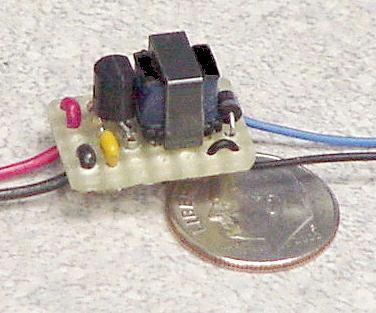